Restoration
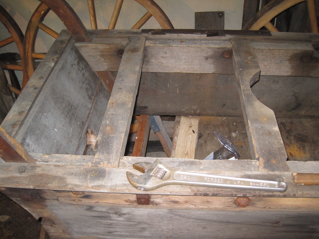
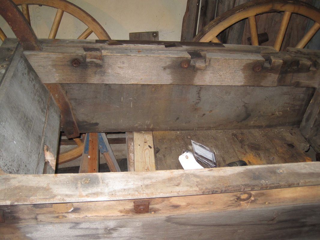
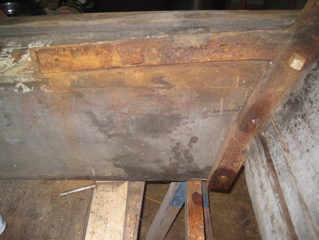
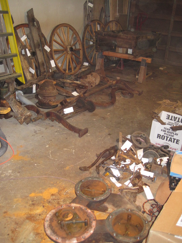
The first part of any restoration is to document and record the existing condition of the project. Digital photos make it really easy. These are just a few of dozens of photos. Here is what it looks like:
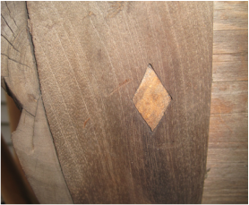
The wheels were rebuilt by a previous owner who apparently had planned to restore it. That saves me a ton of money because I am no wheelwright, at least I don't think so. They were very well done and are in great shape. The trim molding on the tub portion is mahogany, as are the top cover pieces. There are missing and unsalvageable pieces of each. At some time this spent many years out in the weather.

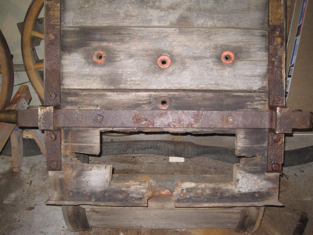
The diamond shaped holes are where the trim is attached to the tub with countersunk screws.
Each hole would be covered with a diamond shaped wood plug of a contrasting color. Just a few are left. |
|
Once in the shop I start by removing all of the mahogany trim and the top. Each piece is tagged as to its location. Nothing is discarded. While removing the trim, bits of veneer is found underneath. The box was apparently originally veneered but nearly all has been weathered off. The veneer is also mahogany.
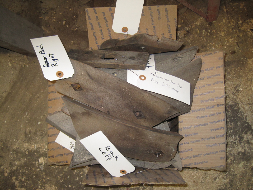
Box of mahogany tub trim pieces
|
|
|
Update 11/26/2012:
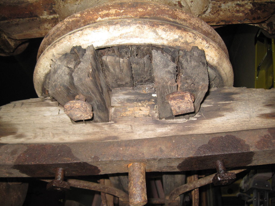
Once the trim is removed, the next step is to remove the interior structural wood framing. First the rear wheels are removed for easier access and the back of the handtub is placed on jackstands. The wheels have simple bushing style bearings. Most of the interior framing is to support the top cover of the tub. These pieces just drop into keyed notches in the main side beams and simply lift out. The rearmost cross member is missing. I will make a new one based on the size of the notches. One crossmember appears to be an earlier replacement since it is a different kind of wood and is rather crudely formed. Most of the pieces are relatively solid, showing only significant weathering. However, the largest crossmember, which supports the rear rocker arm bearing column, is badly rotted. This crossmember, which takes much of the stress of the pumping action, has two wood support columns from the floor of the tub. It is also held down with 4 bolts which were removed when the previous owner removed the pump. Fortunately, most of the loose parts that came with this were also tagged by the previous owner. All of the interior framing is white oak. The interior side beams are attached to the tub sides with carriage bolts. Liberal application of penetrating oil and plenty of patience allows these bolts to be removed undamaged. Again, all pieces, including hardware, are tagged as they are removed. Underneath the beams are horizontal arms of the front crane frame. These fit into grooves cut into the back of the side beams. The carriage bolts that held the oak beams pass through holes in these arms. There are additional bolts that attach the arms to the side of the tub and these are now exposed. More pentrating oil and patience.
Once the trim is removed, the next step is to remove the interior structural wood framing. First the rear wheels are removed for easier access and the back of the handtub is placed on jackstands. The wheels have simple bushing style bearings. Most of the interior framing is to support the top cover of the tub. These pieces just drop into keyed notches in the main side beams and simply lift out. The rearmost cross member is missing. I will make a new one based on the size of the notches. One crossmember appears to be an earlier replacement since it is a different kind of wood and is rather crudely formed. Most of the pieces are relatively solid, showing only significant weathering. However, the largest crossmember, which supports the rear rocker arm bearing column, is badly rotted. This crossmember, which takes much of the stress of the pumping action, has two wood support columns from the floor of the tub. It is also held down with 4 bolts which were removed when the previous owner removed the pump. Fortunately, most of the loose parts that came with this were also tagged by the previous owner. All of the interior framing is white oak. The interior side beams are attached to the tub sides with carriage bolts. Liberal application of penetrating oil and plenty of patience allows these bolts to be removed undamaged. Again, all pieces, including hardware, are tagged as they are removed. Underneath the beams are horizontal arms of the front crane frame. These fit into grooves cut into the back of the side beams. The carriage bolts that held the oak beams pass through holes in these arms. There are additional bolts that attach the arms to the side of the tub and these are now exposed. More pentrating oil and patience.
Crossmembers #1 and #2
|
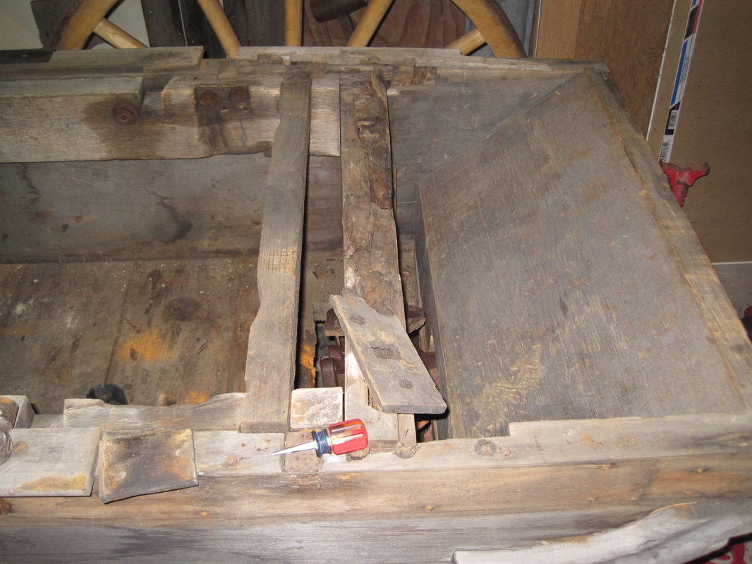
Badly rotted rear crossmember
|
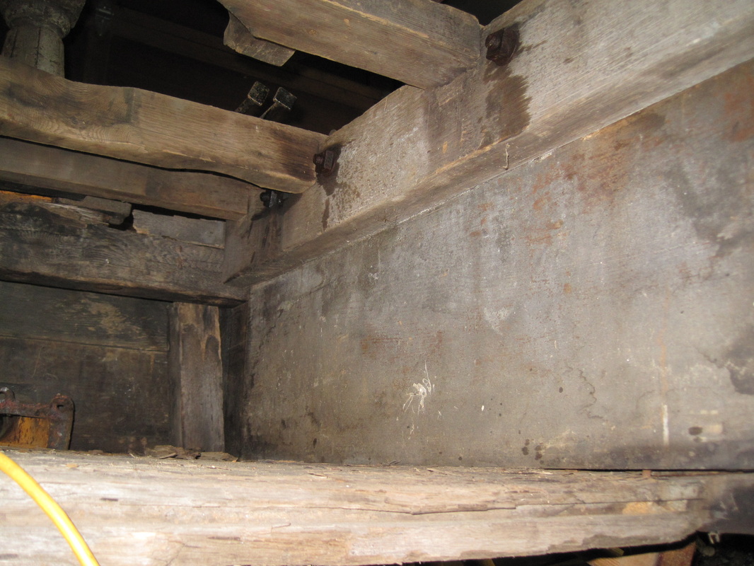
View from below
|
Main side beam
|
Crane frame exposed
|
Update 12/3/2012:
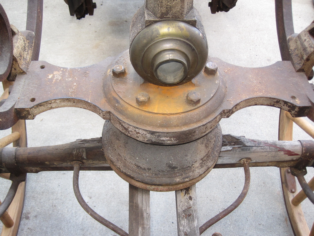
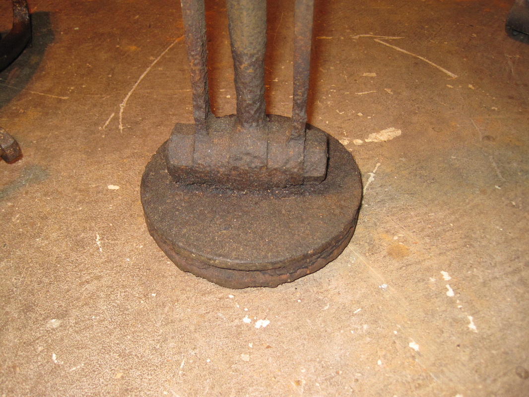
Before the Crane arms can be removed the front axle and fifth wheel must be removed. The "fifth wheel" is the assembly that permits the front axle to pivot. It is essentially two iron disks that rotate against each other. A large iron pin, called the kingpin or kingbolt, goes through the center of each and holds them in place. First I remove the front rocker arm bearing support which gives access to the kingpin. This column also contains the discharge hose connection. The piping has been cut off. I support the front axle on jackstands and remove the front wheels. Then I support the front of the tub on a short sawhorse and pull out the kingpin. The front axle is now released from the handtub and I can move it aside. Next I need to remove the front crossmember that attaches between the crane arms and is the upper section of the fifth wheel. There are 3 large bolts on each side. One of these bolts along with a smaller bolt hold the front rocker arm bumper on each side. These bumpers, which have rubber inserts, limit the stroke of the brakes at both the front and rear of the handtub. In removing all of these bolts, which thread into tapped holes in the crossmember casting, I twist off 2 of them (*#&!). The steel used then was very soft. These are 5/8" bolts and I wasn't even using a cheater bar. Replacing these bolts, or most any of the hardware, is not easy. Bolt heads were much larger and thicker than they are today and there were no strength marks on the heads. These bolts also have domed heads. Anyway, this large casting (over 100 lbs.) is now loose and is set aside.
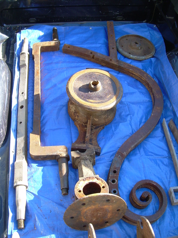
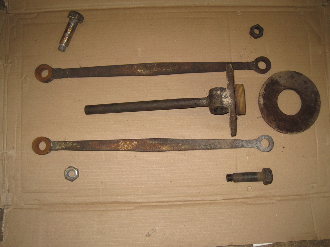
Back to the front axle, which is an iron axle backed up by wood and includes the arms that attach to the tongue as well as the lower disk of the fifth wheel. The wood here is well rotted and there is just enough left to extrapolate a pattern. Also attached to the front axle is the rope reel that holds the drag ropes for the fireman that would pull this. The tongue is missing.
Before the Crane arms can be removed the front axle and fifth wheel must be removed. The "fifth wheel" is the assembly that permits the front axle to pivot. It is essentially two iron disks that rotate against each other. A large iron pin, called the kingpin or kingbolt, goes through the center of each and holds them in place. First I remove the front rocker arm bearing support which gives access to the kingpin. This column also contains the discharge hose connection. The piping has been cut off. I support the front axle on jackstands and remove the front wheels. Then I support the front of the tub on a short sawhorse and pull out the kingpin. The front axle is now released from the handtub and I can move it aside. Next I need to remove the front crossmember that attaches between the crane arms and is the upper section of the fifth wheel. There are 3 large bolts on each side. One of these bolts along with a smaller bolt hold the front rocker arm bumper on each side. These bumpers, which have rubber inserts, limit the stroke of the brakes at both the front and rear of the handtub. In removing all of these bolts, which thread into tapped holes in the crossmember casting, I twist off 2 of them (*#&!). The steel used then was very soft. These are 5/8" bolts and I wasn't even using a cheater bar. Replacing these bolts, or most any of the hardware, is not easy. Bolt heads were much larger and thicker than they are today and there were no strength marks on the heads. These bolts also have domed heads. Anyway, this large casting (over 100 lbs.) is now loose and is set aside.
Back to the front axle, which is an iron axle backed up by wood and includes the arms that attach to the tongue as well as the lower disk of the fifth wheel. The wood here is well rotted and there is just enough left to extrapolate a pattern. Also attached to the front axle is the rope reel that holds the drag ropes for the fireman that would pull this. The tongue is missing.
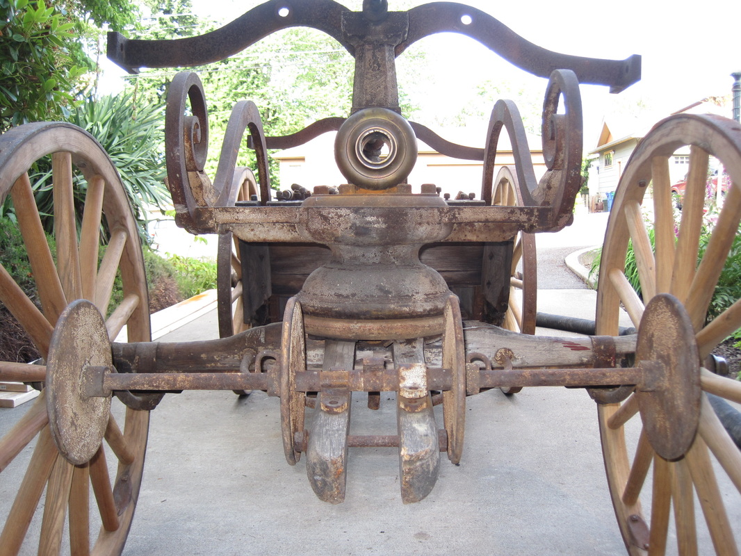
Front axle assembly with fifth wheel
|
Bolts holding the front rocker bearing column
|
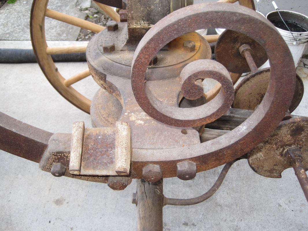
Those *&#! bolts
|
View of front axle assembly from the bottom
|

Bottom view of the lower fifth wheel
|
Update 12/10/2012:
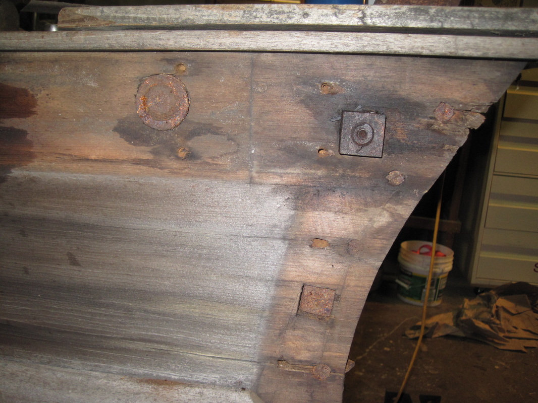
With the front truck and crossmember removed, the crane arms can now be unbolted from the wooden tub.
The penetrating oil has had time to work and the bolts come apart easily. The arms are removed and
set aside. Next to remove is the rear axle. This also is iron and attaches directly to the bottom of the tub. There are iron brackets that secure the axle in place to the tub sides in addition to a couple of carriage bolts through the axle and the bottom of the tub. The brackets must be removed before the axle can be removed.
The tub is fairly light now and I can stand it up on end to reach everything easier. Each bracket is held on by 3 lag bolts and 2 long bolts that run clear up inside the sides of the tub to the top. The brackets come off and go into the parts pile. Next are the carriage bolts. These are pretty well rusted and being carriage bolts there is no way to put a wrench on the heads. These bolts are badly rusted and need to be replaced anyway so I cut the nuts off of the bottom and drive the bolts out and remove the axle. All the bolts are tagged or go into labeled envelopes. Of the 4 long bolts that run up through the sides of the tub, only one can be removed. The other 3 are apparently rusted tight to the wood. I try hammering and pressing them out with bar clamps but they won’t budge so I leave them in place. The last hardware to remove from the tub is 2 stay bolts that run crosswise through the tub at the front and back. They have nuts on each end which are recessed into the outside of the tub sides.
The front one is inside the tub where is has been exposed to water and the entire bolt is very rusty. As I turn the nut I can see the bolt twisting in a spiral. It will need to be replaced anyway so I cut it off and pull the ends out each side. I will salvage the nuts. The rear stay bolt is buried deeply in the back of the tub which has kept it dry. The nuts come off easily and the bolt comes out.
I have also been disassembling the pump. I began applying penetrating oil to this as soon as it was in the shop. The pump is a piston type pump with two cylinders and a pressure chamber. Each piston has a rigid piston rod that slides within a guide attached to the top of the cylinder. The are also 2 connecting rods on each piston that pivot and are attached to the rocker arm at their upper end. The valves are poppet style valves of "gun metal" which is an alloy of copper, tin, and zinc. The suction valve is located at the bottom of each cylinder and the discharge valves are located in the pressure chamber. The cylinders are brass. The main pump body and pressure chamber are cast iron. The pressure chamber and cylinders come off easily. The valve plates are now accessible as well as the pistons. I apply penetrating oil to these and set them aside.
So now most everything is disassembled. This is the point that my wife always comes into the shop and says " I sure hope you know how to put this back together."
Rear axle
|
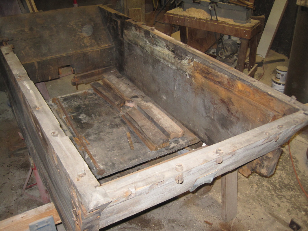
Bare tub after all iron is removed
|

Pump assembly, pistons at left
|
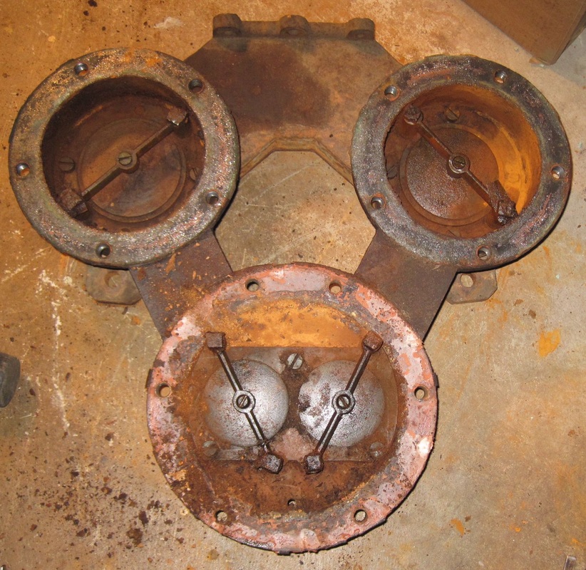
Pump body with valve plates exposed
|
|
Update 12/17/2012:
Now that most everything is disassembled it is time to start cleaning. Since nothing can be easily replaced everything that is salvageable, including nuts and bolts, needs to be cleaned and reused. Unlike my motorized pumper, there is very little grease and dirt to clean off. All of the smaller parts can go directly into the sandblasting cabinet. The larger parts will go off to a company that electrochemically dips the parts to remove paint and rust. There is very little of the original paint left on any of the parts.
I document any of the original decoration that remains with photos and notes so that it can be reproduced.
The original paint is cream with deep red and green striping. Once the parts are sandblasted, I treat them with a metal prep solution otherwise they will immediately begin to rust again. Since I do have a day job, it takes several evenings and the weekend to sandblast all of the small parts that have been disassembled so
far.
I also begin to figure out what materials I need to build the new tub. The interior framing is all white oak which is readily available. Most of the tubs were built of solid mahogany but this one is
veneered, presumably as a cost cutting measure. The tub itself is a softwood and being built in NY I suspect it is white pine. I consult with a local antique furniture restorer and he confirms my suspicions. The wood is almost completely clear with only a couple of very small knots. The sides are also one single piece, 2” x 16”x 72”. The tub bottom is also 2” thick oak with spline joints. The tub itself is held together with wood screws and the two stay bolts.
I am still working on disassembling the pump components, which are being very uncooperative.
It is apparent that when this sat outside the pump cylinders, which are open on top, filled up with water causing major rust to the piston assemblies. I can remove the nuts from the lower connecting rod bolts but the bolts themselves will not budge. But I can get penetrating oil into the joint now. The heads of the bolts which hold the valve guides in place are also very rusted and cannot hold a wrench. I am able to grind the heads off and remove the valves.
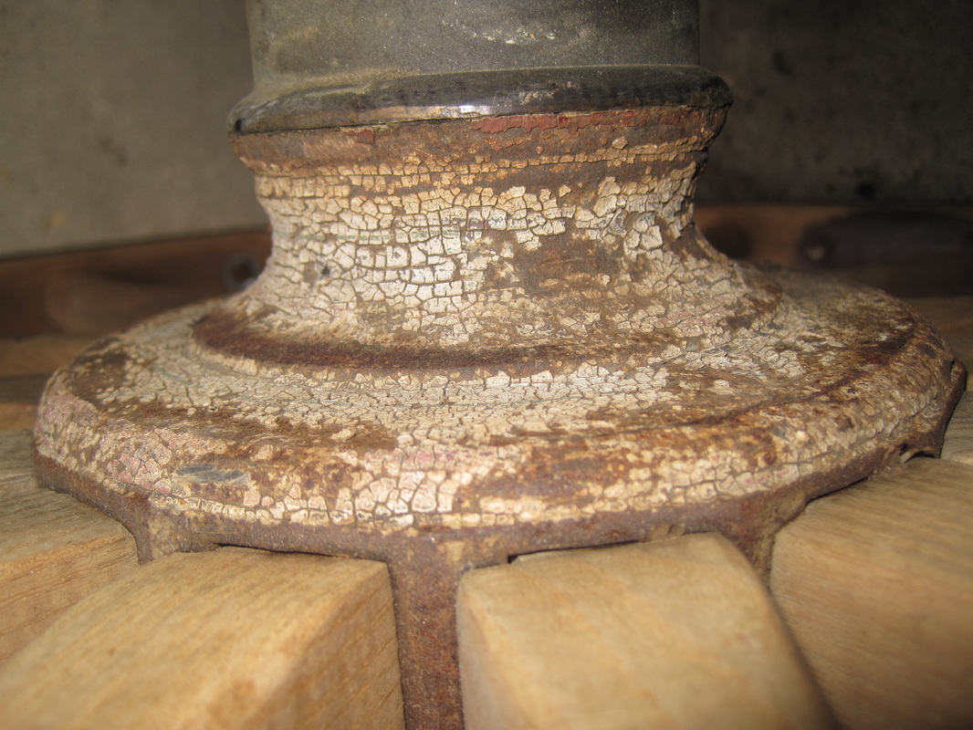
Wheel hub showing original red and green striping
|
First load to the metal stripper
|
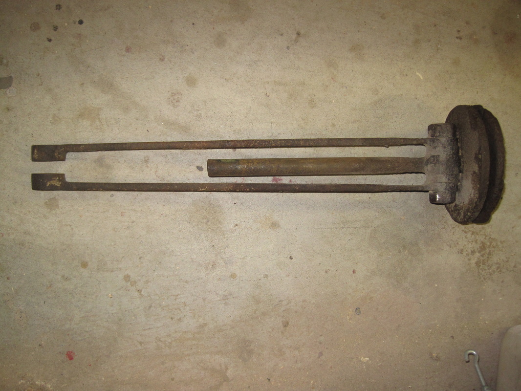
Piston and connecting rods
|
Rusted lower connecting rod bolt
|
Update 1/7/2013
Through a combination of heating, rust remover, and penetrating oil the lower connecting rod bolts have come loose so now the piston assemblies are apart. Both the piston rod and connecting rods are very rusted at the bottom end and will require welding to build them up to their original dimensions. I forgot to mention that all that is left of the original leather pump seals is just a few crumbs. I will need to do some research to figure out what they looked like and then make replacements.
I have now sandblasted most of the small parts including the salvageable hardware.
I prepare a materials list of all of the lumber I need and after visits to a couple of local hardwood lumber suppliers, I find nearly everything I need is in stock at Crosscut Hardwoods.
On my first visit I get all of the oak I need to the structural framing. I cut the oak pieces to the basic overall dimensions of the originals leaving the final fitting until the new tub is built.
I also begin searching for replacement hardware. When this was built, hardware (fasteners, technically) were much different than modern fasteners. Most bolts and nuts had square heads and the bolt heads as well as the nuts were much thicker. They were black steel, not zinc plated and they had no strength marks on the heads. And of course, there was no such thing a Phillips head screw. I found a great supplier, Blacksmith Bolt, just a couple of miles from my house so I place my order. Sorry, no in person pickup I’m told but USPS delivers it the next day.
I also make the new stay bolts, both the 4 vertical ones and the one horizontal one. The vertical ones are 1/2" round rod with a flat plate on top and threaded on the bottom. I cut the small rectangular plates out of some scrap iron laying around and weld them onto the round rod and thread the bottom ends and they are done. The horizontal one is just a 1/2" round rod threaded on both ends.
Piston and connecting rods disassembled.
|
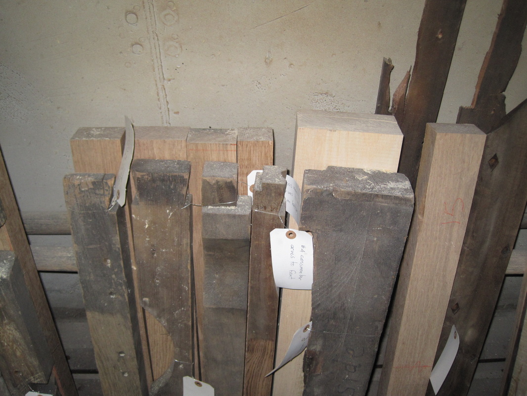
Structural framing pieces with roughed out replacements
|
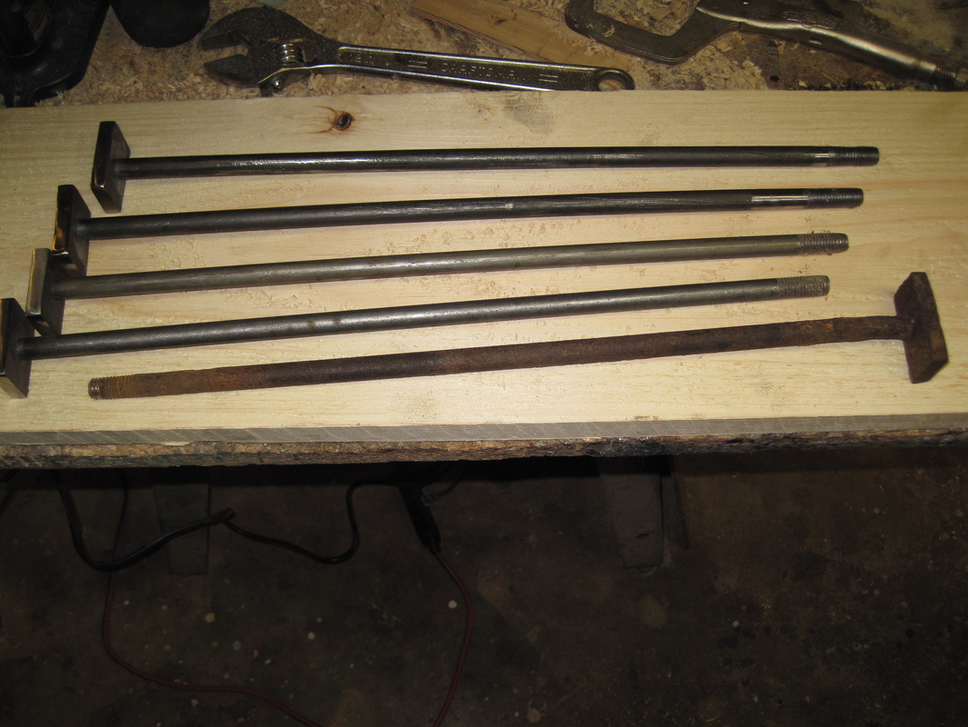
One old vertical stay bolt and the 4 new ones.
|
Update 1/19/2013
The piston and connecting rods can now go into the sandblaster. As noted previously, the connecting rods are badly rusted and pitted at the bottom end. In order to repair the damage it is neccesary to add metal back to the pitted areas by welding. After welding they are ground to the approximate original profile and will be finished by hand filing.
The first load of parts come back from the stripper with all the rust and old paint removed.
I cut and shape the wood pieces for the front axle assembly. After cutting the wooden axle to the overall dimensions I cut slots into the top the proper depth to match the curve and then I knock out the sections between with a hammer and chisel. I use a coarse sanding disk on my angle grinder to smooth and round the top edge to the proper shape. The front and rear surfaces of the axle also taper towards the ends and I use a plane to cut the tapers. The pieces that attach to the tongue are rounded on the outside edges and I use the disk sander to form those. I then cut the notches in these 3 pieces so they fit together.
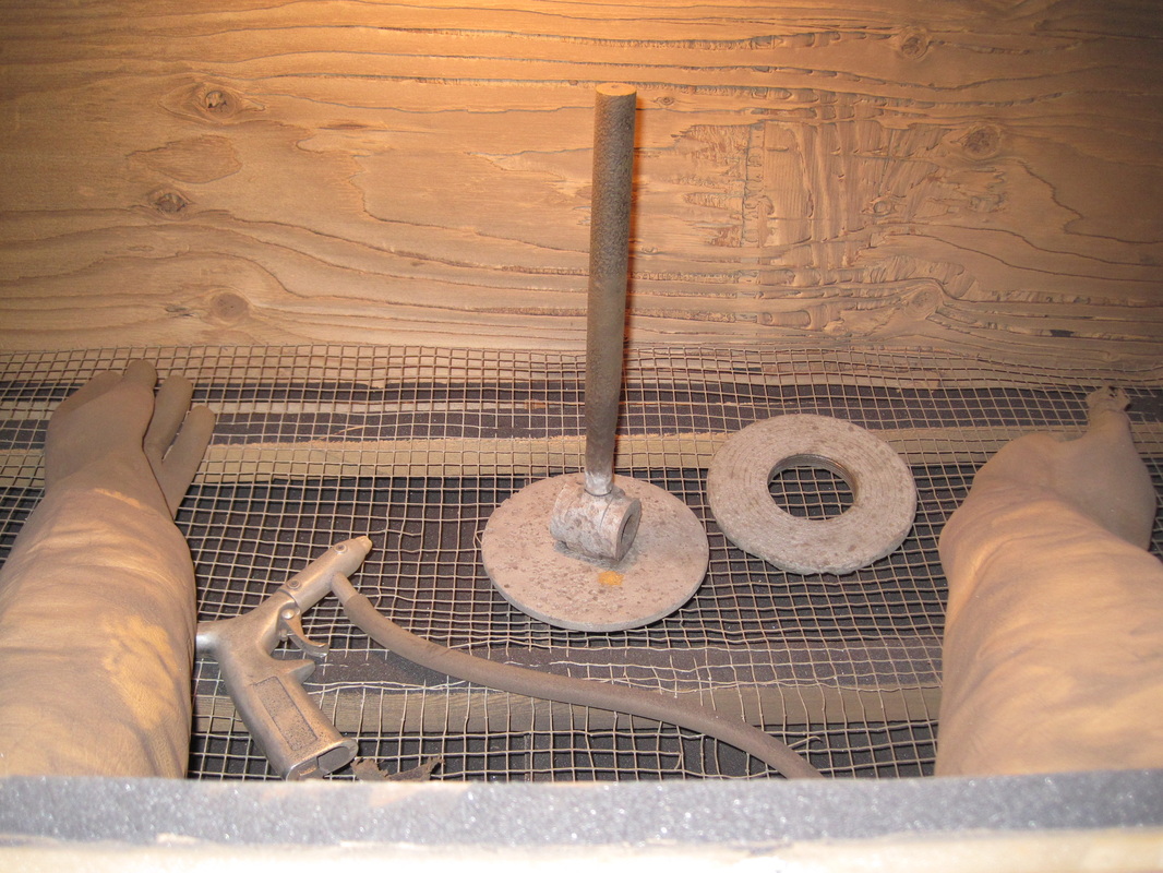
Piston in the sandblaster
|
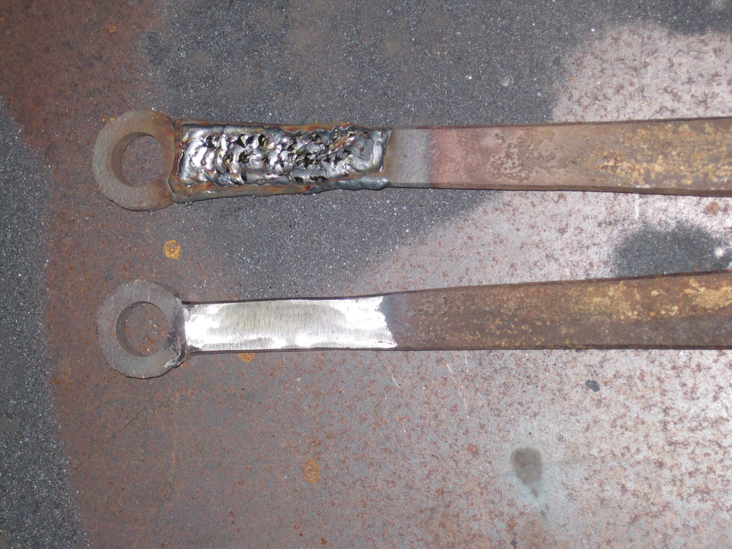
Connecting rod welded (top) and ground to profile
|
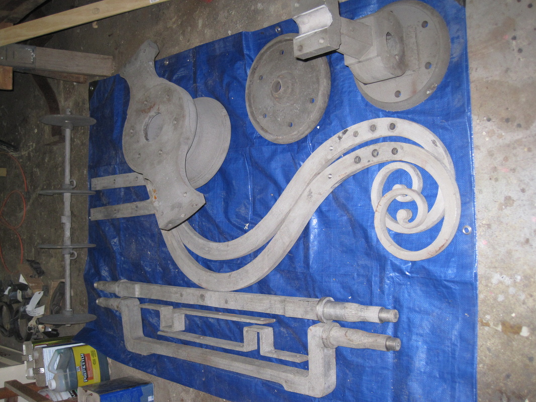
Parts back from metal stripper
|
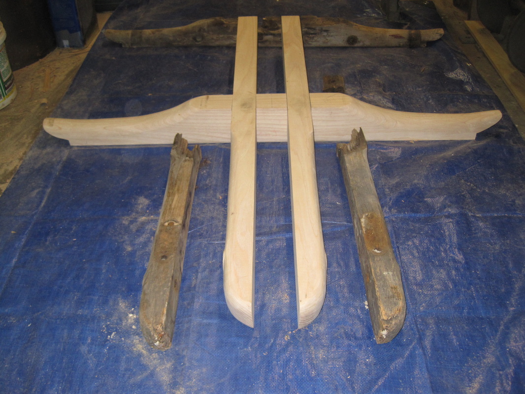
Front axle assembly wood
|