Update 10/9/2013
Well, the summer reenacting/fire engine show/parade season is over and the weather is changing. So time to get back to work on the project. Over the summer I was able to spend some time now and then working on it. I found time to paint the wheels. I sanded and primed them and then painted with 3 coats of spar enamel, sanding between each coat with progressively finer sandpaper.
Well, the summer reenacting/fire engine show/parade season is over and the weather is changing. So time to get back to work on the project. Over the summer I was able to spend some time now and then working on it. I found time to paint the wheels. I sanded and primed them and then painted with 3 coats of spar enamel, sanding between each coat with progressively finer sandpaper.
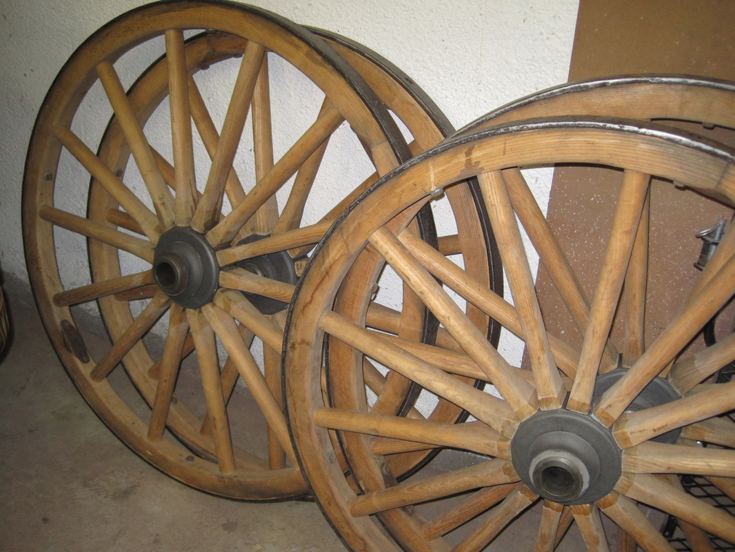
Bare wheels
|
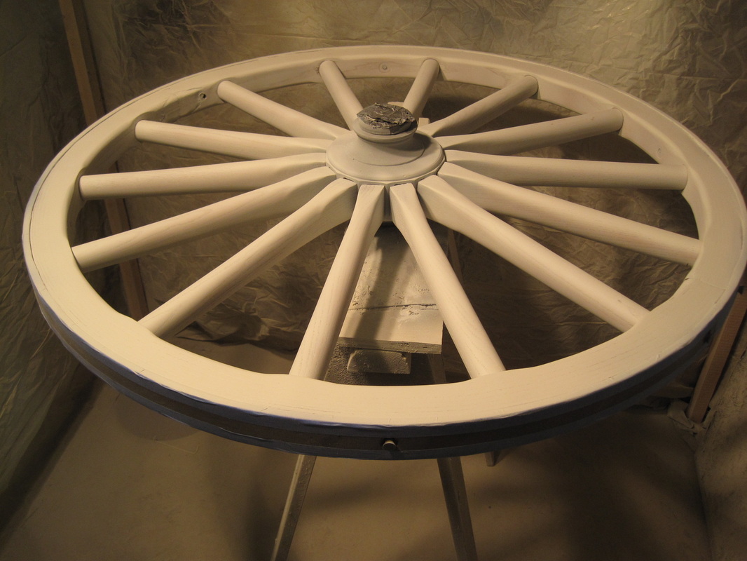
Primer coat
|
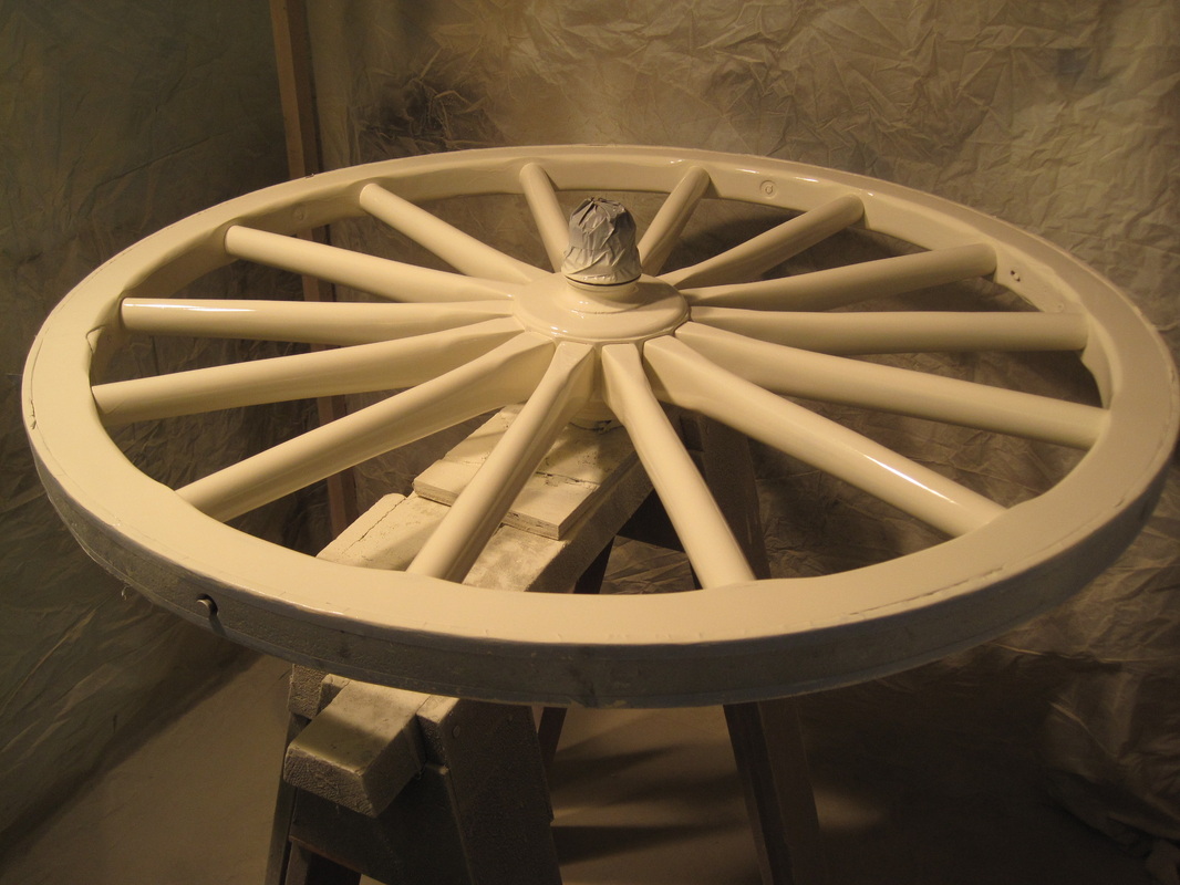
Finish coat
|
Update 11/20/2013
I'm continuing to apply the finish paint to the metal parts. As I complete them I add any striping or decoration that would be difficult to do when it is assembled, matching the original design. The rear axle is painted, striped and attached to the tub. I then attach the crane arms to the tub which allows me to finish installing the wood framing inside the tub. Once the crane arms are on I can assemble and attach the fifth wheel assembly and front axle, along with the drag rope reels. With both axles on I can now attach the wheels and it is mobile once more.
I'm continuing to apply the finish paint to the metal parts. As I complete them I add any striping or decoration that would be difficult to do when it is assembled, matching the original design. The rear axle is painted, striped and attached to the tub. I then attach the crane arms to the tub which allows me to finish installing the wood framing inside the tub. Once the crane arms are on I can assemble and attach the fifth wheel assembly and front axle, along with the drag rope reels. With both axles on I can now attach the wheels and it is mobile once more.
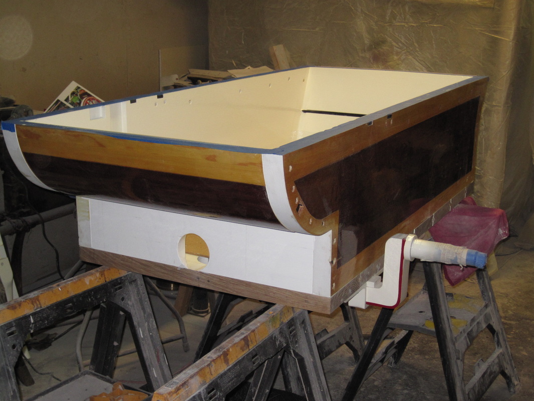
The tub assembled with the rear axle attached.
|
Part with striping painted.
|
Partially assembled with wheels attached.
|
Update 12/21/2013
With the tub mostly assembled I go back to work on the pump. Most of the larger pieces are cast iron and have been stripped. Using a disk sander I clean up any gasket mating surfaces where the pieces bolt together. The pump is hidden from view inside the tub and they were typically painted black. Sources note that since the pump was frequently disassembled for service, any chips in the black paint could be easily touched up with readily available paint. I paint the inside and outside of all of the iron parts with gloss black paint. There are 4 valves inside the pump. Each cylinder has a suction inlet valve at the bottom of the cylinder and a discharge valve in the bottom of the pressure chamber. These are poppet style valves with upper and lower valves guides. The upper guide on one of the discharge valves is both bent and cracked. I carefully bend it back into shape and braze the cracked areas. The discharge valve plate which holds both discharge valves is held down by round-flat head slotted machne screws. I need t make new ones since the originals had to be drilled out during disassembly. Starting with hex head machine bolts I grind the head into a round shape and cut a slot with a hacksaw. The head is just slightly thinner than the original. The remainder of the bolts holding the valve plates and guides together are standard hex head brass bolts that are available. Once the valves are assembled I lap the valves. Using valve grinding compound, which is an abrasive paste, between the valve and the valve seat, the valve is rotated in the guides. This removes any irregularities in the valve and seat surfaces, allowing them to mate well, thus minimizing any leakage. The valve stems have slots in them just for this purpose so a drill with a screwdriver bit makes the process much faster then the original method which consisted of holdng a screwdriver between one's palms and rotating it back and forth.
With the tub mostly assembled I go back to work on the pump. Most of the larger pieces are cast iron and have been stripped. Using a disk sander I clean up any gasket mating surfaces where the pieces bolt together. The pump is hidden from view inside the tub and they were typically painted black. Sources note that since the pump was frequently disassembled for service, any chips in the black paint could be easily touched up with readily available paint. I paint the inside and outside of all of the iron parts with gloss black paint. There are 4 valves inside the pump. Each cylinder has a suction inlet valve at the bottom of the cylinder and a discharge valve in the bottom of the pressure chamber. These are poppet style valves with upper and lower valves guides. The upper guide on one of the discharge valves is both bent and cracked. I carefully bend it back into shape and braze the cracked areas. The discharge valve plate which holds both discharge valves is held down by round-flat head slotted machne screws. I need t make new ones since the originals had to be drilled out during disassembly. Starting with hex head machine bolts I grind the head into a round shape and cut a slot with a hacksaw. The head is just slightly thinner than the original. The remainder of the bolts holding the valve plates and guides together are standard hex head brass bolts that are available. Once the valves are assembled I lap the valves. Using valve grinding compound, which is an abrasive paste, between the valve and the valve seat, the valve is rotated in the guides. This removes any irregularities in the valve and seat surfaces, allowing them to mate well, thus minimizing any leakage. The valve stems have slots in them just for this purpose so a drill with a screwdriver bit makes the process much faster then the original method which consisted of holdng a screwdriver between one's palms and rotating it back and forth.
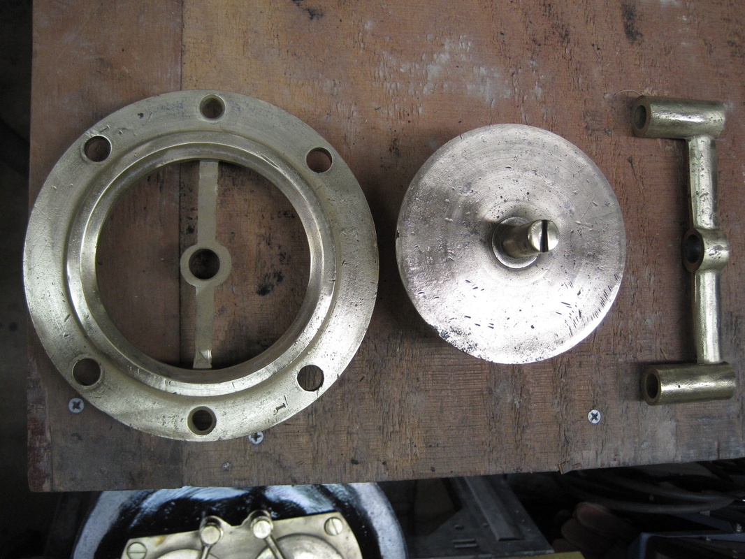
Lower valve guide and seat, valve disc, and upper guide.
|
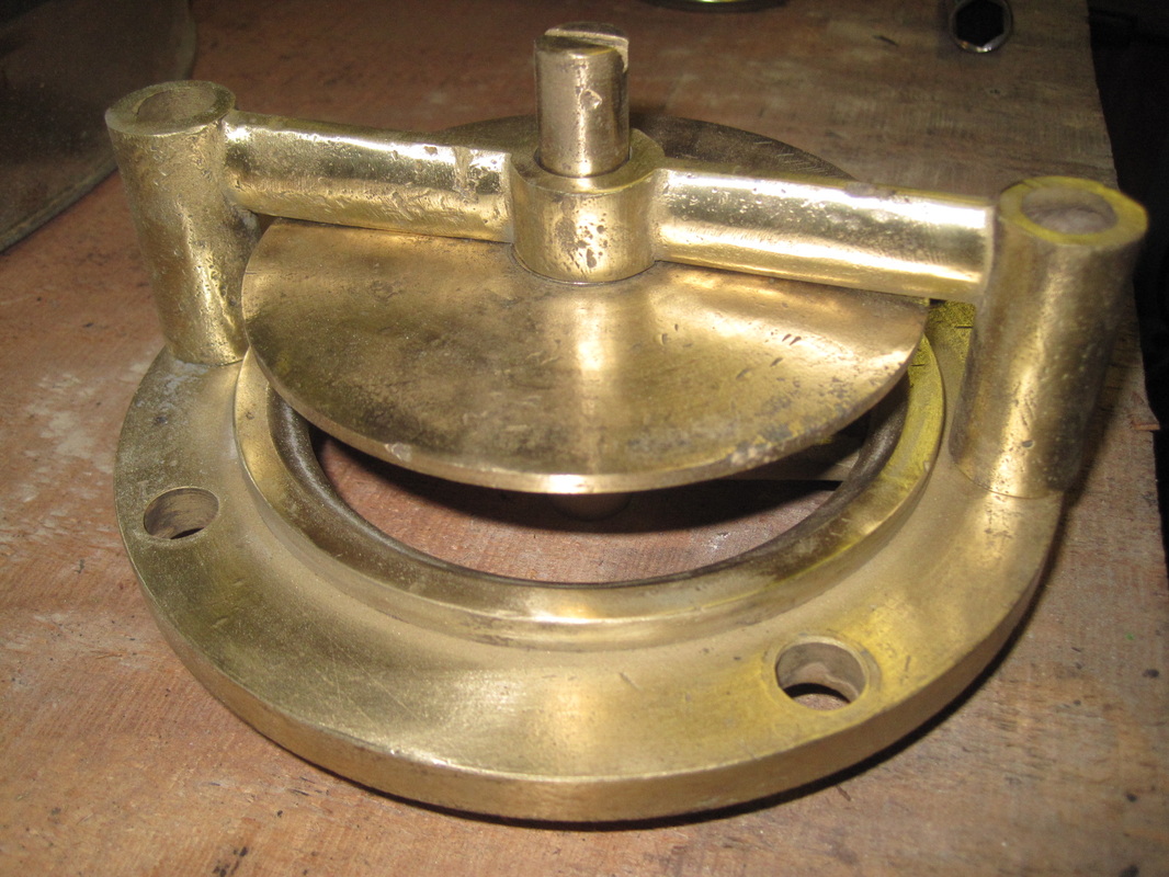
Suction valve in open postion.
|
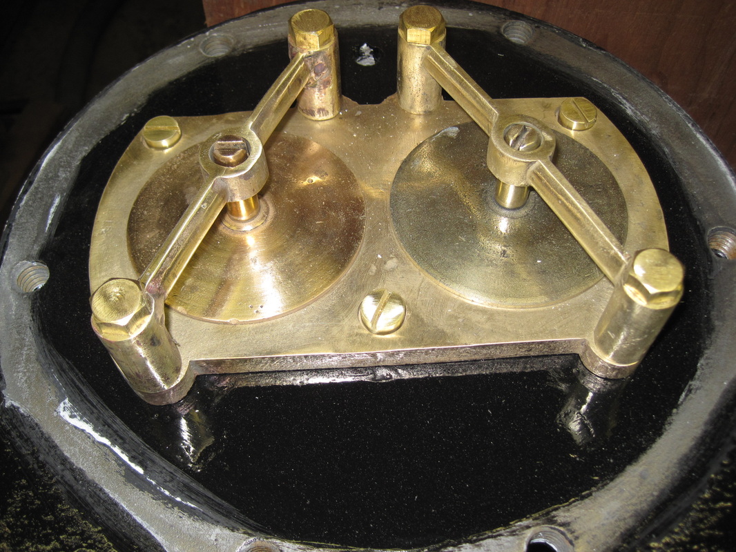
Discharge valves assembled and installed in the bottom of the pressure chamber.
|
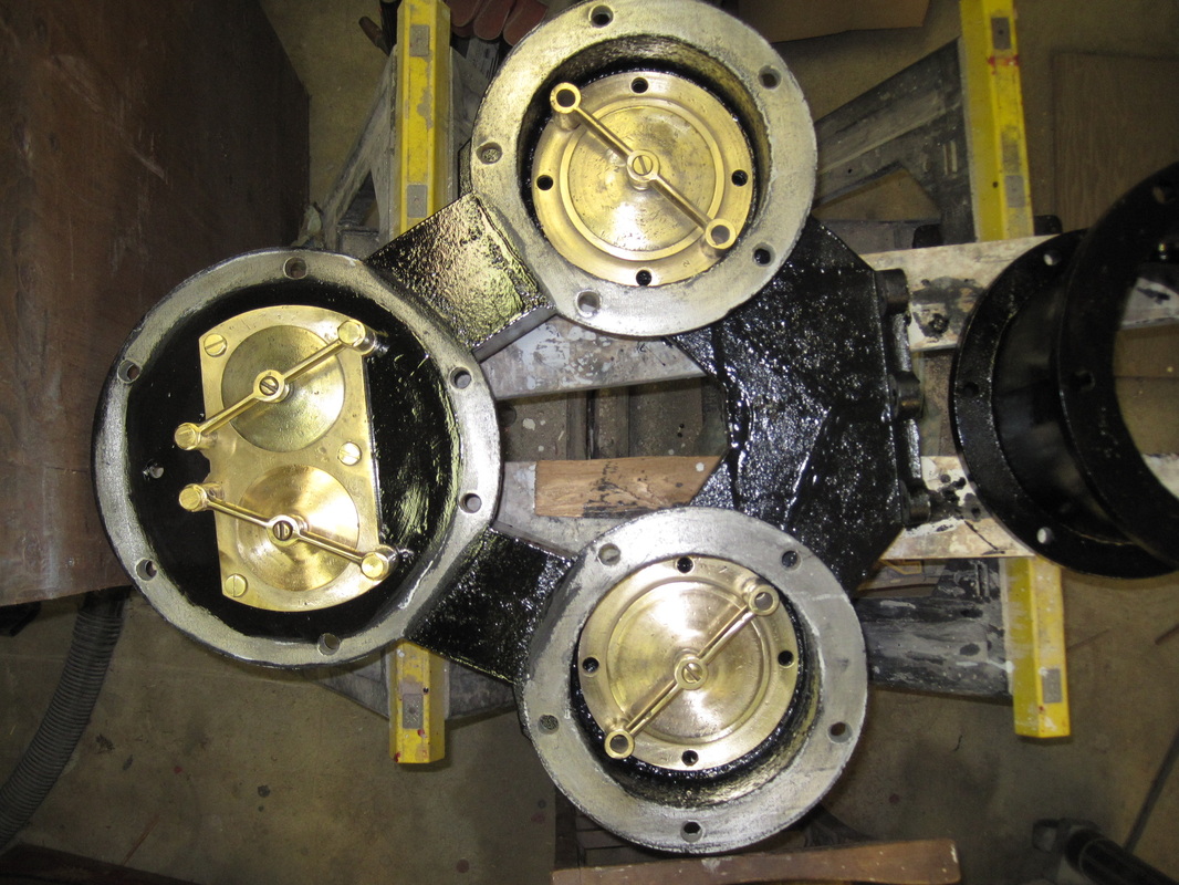
Pump body with all valves installed.
|
Update 1/20/2014
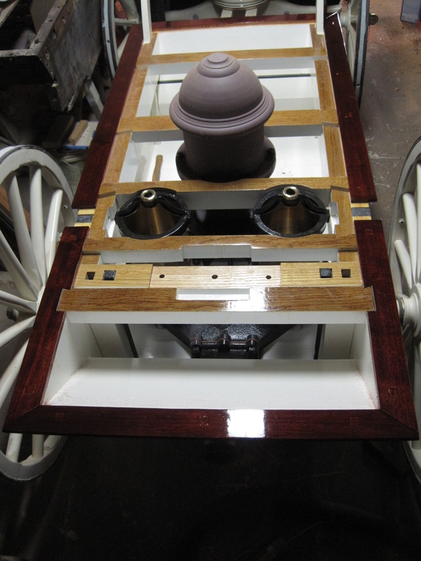
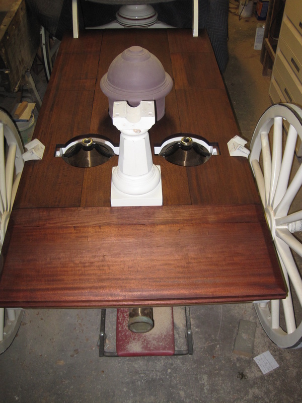
With the valves installed back in the pump I now move the pump back into the tub. Once it is back in I bolt on the suction inlet and then slide it into place with the suction hose connection sticking out the back of the tub. I carefully center the pump in the tub and drill the mounting bolt holes through the tub bottom. After bolting the pump down I mark and cut new gaskets for the pump and air chamber flanges, using red rubber sheet gasket material to match the original. With the gaskets in place I bolt the pump cylinders and the bottom portion of the air chamber in place. Once that is all finished I can't resist setting the top part of the air chamber in place to see how it all looks.
I have located the genuine mahogany lumber I need to reproduce the top. Genuine mahogany is the type indigenous to South America. It is also called Honduran Mahogany and is what would have been used originally. Since it was overharvested in the past, it is in limited supply, and correspondingly priced. Most mahogany used now comes from other continents and is a different species. Mahogany was used in handtub construction for many of the same reasons it was used for boatbuildng. It is light, strong, easy to work, rot resistant, and very beautiful. It is a 2 hour drive each way to get the lumber but I find all that I need and it is very good quality, virtually knot free.
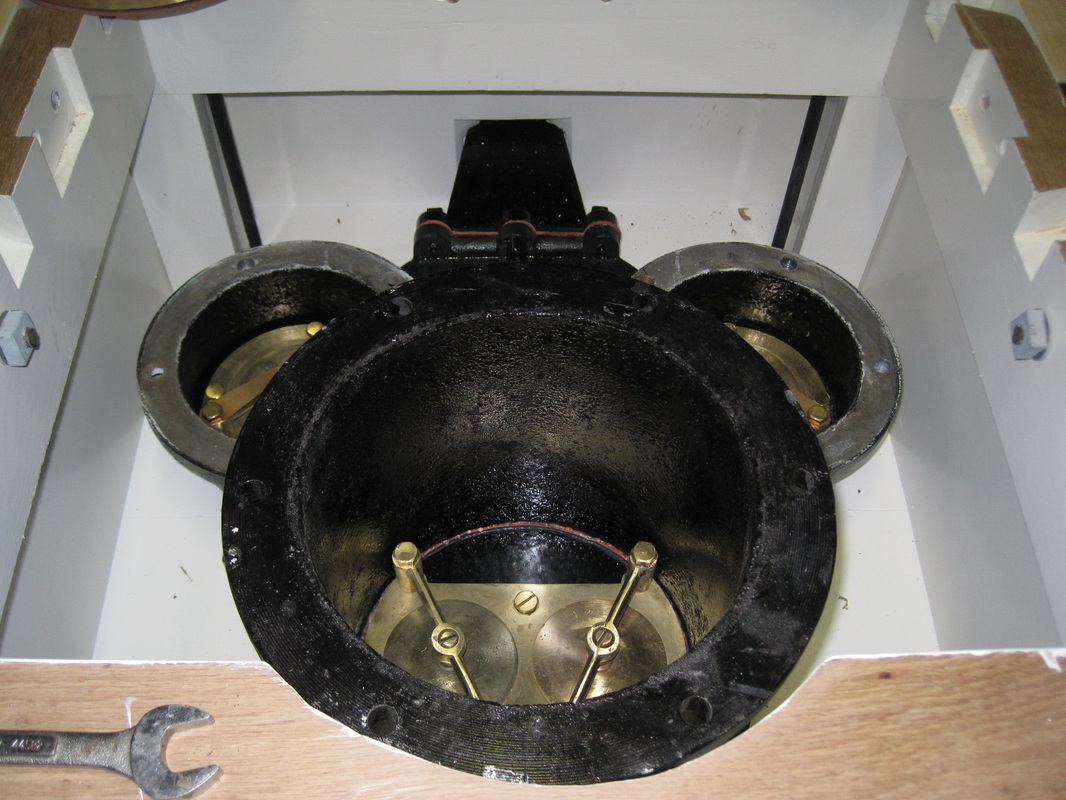
Pump in place with the bottom portion of the air chamber installed.
|
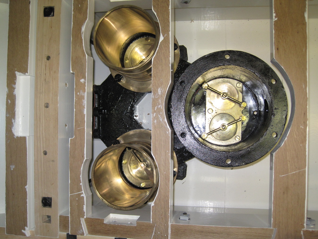
Pump cylinders installed on pump.
|
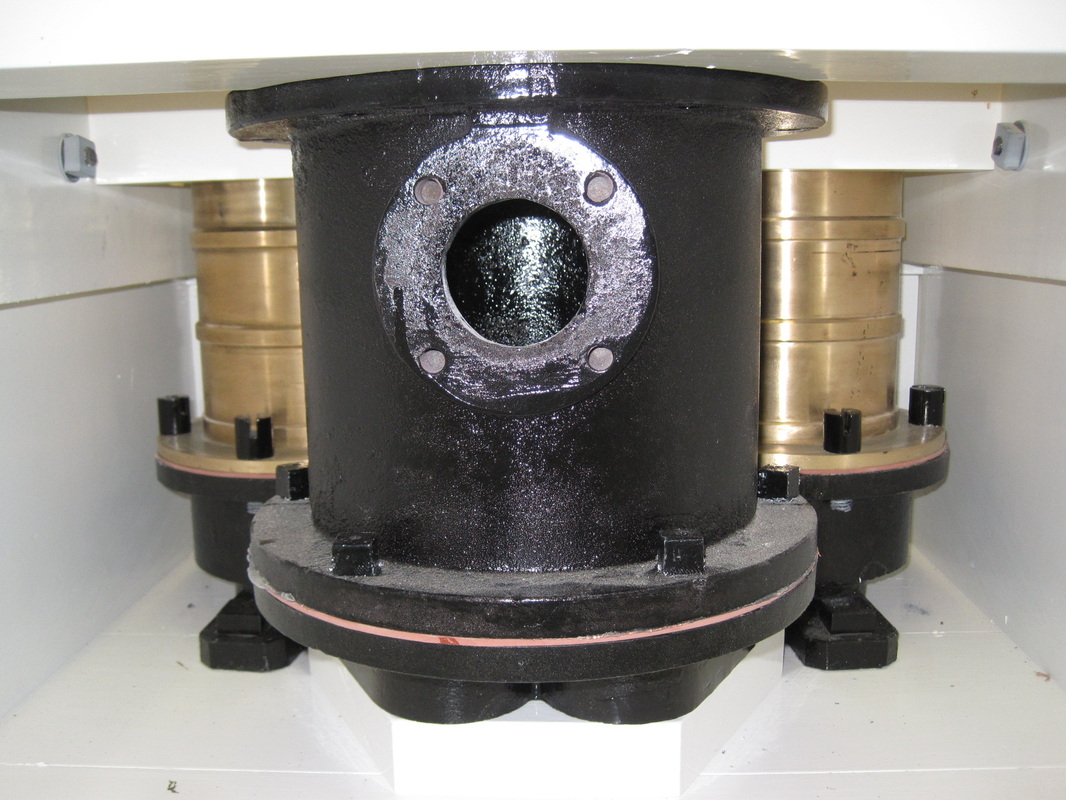
Front view of pump with discharge flange.
|
|
Update 3/14/2014
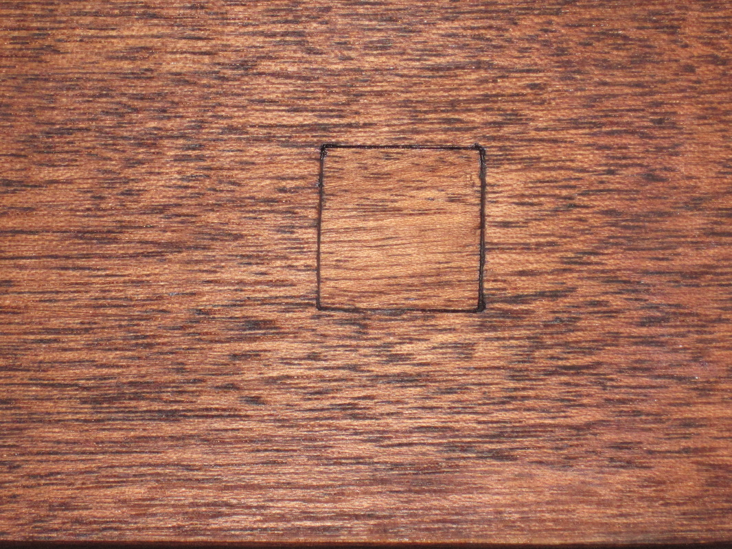
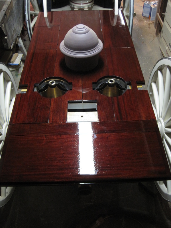
After installing the pump, hopefully for the last time, I make some final adjustments to the top framing pieces, clean any white paint off of the top surface and apply a couple of coats of spar varnish. Next is making the pieces of trim that covers the top edge of the pine tub sides. These pieces were mahogany so I take some of the 1" thick mahogany boards to a local woodworking shop to have them planed to the proper thickness for these pieces as well as some other pieces I will need shortly. After cutting them to the proper size with mitered corners I varnish the bottom surface and attach them to the tub. They are attached with flathead wood screws in countersunk holes recessed within a square cutout. I drill and countersink the holes first and attach the pieces to the tub and then chisel out the square recess. With all the square recesses cut I make the square wood plugs that fit the recesses to cover the screws. The plugs are fairly thin and are not held securely in place by friction as is normal for wood plugs. Like the diamonds that will go on the other trim, these will be held in place by the coats of varnish. I have also done some color matching tests on the original pieces of mahogany trim that I will be reusing. I sand off the weathered surface to get down to the true color of the mahogany, which has darkened throughout due to aging and oxidation. I varnish a piece as a sample. With some testing, I find it will require 2 applications of mahogany stain in order to make the new wood come close to the same color as the old. I apply two coats of stain to the top trim, insert the plugs and stain them. Then I apply 4 coats of spar varnish to the top and sides of these trim pieces. Too bad this gets mostly covered up by the top.
After installing the pump, hopefully for the last time, I make some final adjustments to the top framing pieces, clean any white paint off of the top surface and apply a couple of coats of spar varnish. Next is making the pieces of trim that covers the top edge of the pine tub sides. These pieces were mahogany so I take some of the 1" thick mahogany boards to a local woodworking shop to have them planed to the proper thickness for these pieces as well as some other pieces I will need shortly. After cutting them to the proper size with mitered corners I varnish the bottom surface and attach them to the tub. They are attached with flathead wood screws in countersunk holes recessed within a square cutout. I drill and countersink the holes first and attach the pieces to the tub and then chisel out the square recess. With all the square recesses cut I make the square wood plugs that fit the recesses to cover the screws. The plugs are fairly thin and are not held securely in place by friction as is normal for wood plugs. Like the diamonds that will go on the other trim, these will be held in place by the coats of varnish. I have also done some color matching tests on the original pieces of mahogany trim that I will be reusing. I sand off the weathered surface to get down to the true color of the mahogany, which has darkened throughout due to aging and oxidation. I varnish a piece as a sample. With some testing, I find it will require 2 applications of mahogany stain in order to make the new wood come close to the same color as the old. I apply two coats of stain to the top trim, insert the plugs and stain them. Then I apply 4 coats of spar varnish to the top and sides of these trim pieces. Too bad this gets mostly covered up by the top.
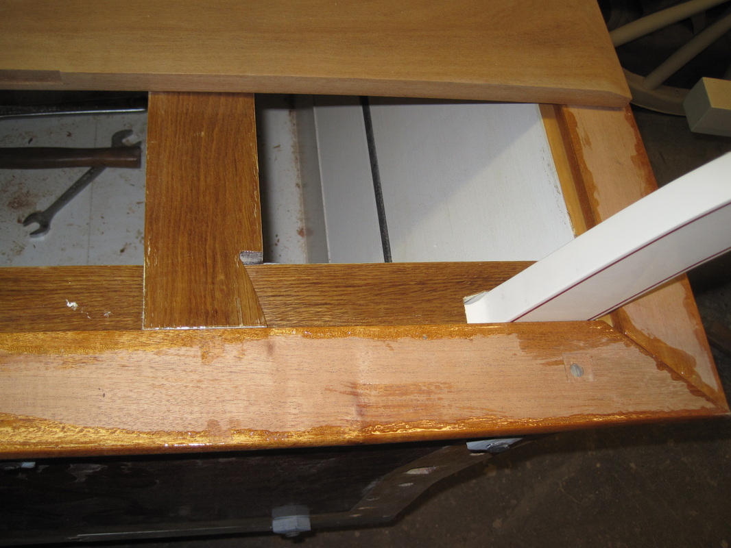
Top trim attached with wood screws.
|
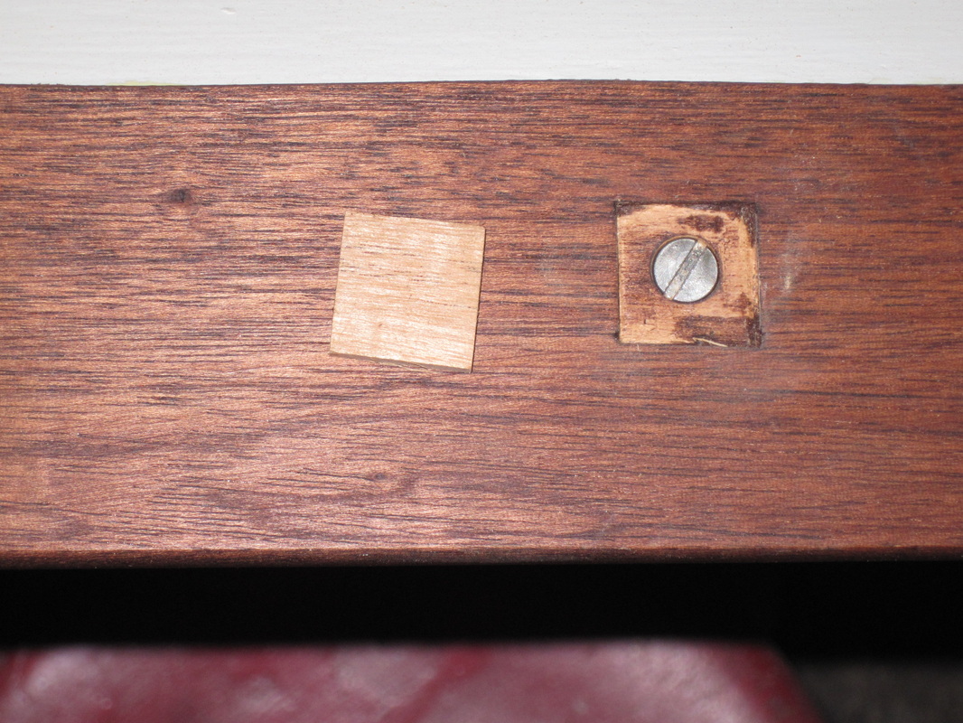
Square recess with countersunk screw and plug.
|
Square plug installed over screw and stained.
|
Top trim installed and varnished.
|
Update 4/18/2014
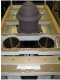
It is finally time to make the top. This is also solid mahogany and consists of several pieces including 3 hinged doors that give access to the interior of the tub. I selected the mahogany lumber so that the shorter pieces are cut from a long piece so that the grain matches. Not all of the original pieces came with the handtub but there were enough to determine the correct size of all of the pieces. It is a straightforward process to cut the boards to the proper length and width and cut a bevel along all of the perimeter edges. I also cut the curved openings to fit around the pump components and also cut the notches for the hinges on the doors. After sanding all of the pieces they get 2 applications of stain and 4 coats of varnish. Once I have completed the restoration I plan on giving these pieces a final sanding and 2 more coats of varnish.
It is finally time to make the top. This is also solid mahogany and consists of several pieces including 3 hinged doors that give access to the interior of the tub. I selected the mahogany lumber so that the shorter pieces are cut from a long piece so that the grain matches. Not all of the original pieces came with the handtub but there were enough to determine the correct size of all of the pieces. It is a straightforward process to cut the boards to the proper length and width and cut a bevel along all of the perimeter edges. I also cut the curved openings to fit around the pump components and also cut the notches for the hinges on the doors. After sanding all of the pieces they get 2 applications of stain and 4 coats of varnish. Once I have completed the restoration I plan on giving these pieces a final sanding and 2 more coats of varnish.
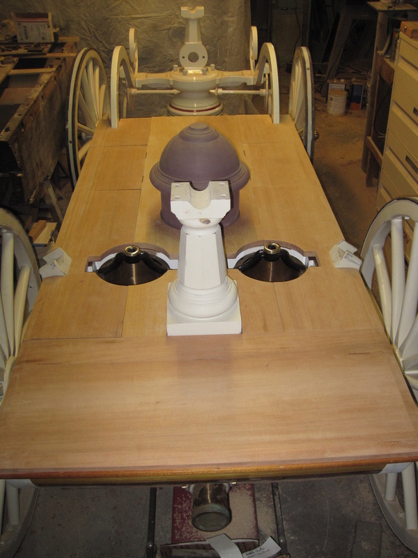
All top pieces cut to size.
|
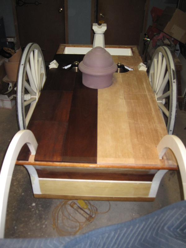
Half of the top stained.
|
Completely stained.
|
After 4 coats of varnish.
|
Update 5/9/2014
The top is attached to the tub framing with screws, of which I have only about one third of the originals, a couple of which are too corroded to reuse. The originals were made by casting a brass head onto a threaded steel screw. I don't have the ability to cast brass so I make the new ones by machining the brass head on my lathe, drilling a hole in the end, and brazing a lag screw (with the head cut off) onto the head. I make 24 new screws which together with the restored originals, is enough for the top. Also needed are large heavy brass washers to go under the screw heads. I cut those out of a sheet of brass with a hole saw on the drill press and clean up the edges with my drum sander. Also, with the warmer weather I can start spray painting again so I prime and sand some more iron pieces.
The top is attached to the tub framing with screws, of which I have only about one third of the originals, a couple of which are too corroded to reuse. The originals were made by casting a brass head onto a threaded steel screw. I don't have the ability to cast brass so I make the new ones by machining the brass head on my lathe, drilling a hole in the end, and brazing a lag screw (with the head cut off) onto the head. I make 24 new screws which together with the restored originals, is enough for the top. Also needed are large heavy brass washers to go under the screw heads. I cut those out of a sheet of brass with a hole saw on the drill press and clean up the edges with my drum sander. Also, with the warmer weather I can start spray painting again so I prime and sand some more iron pieces.
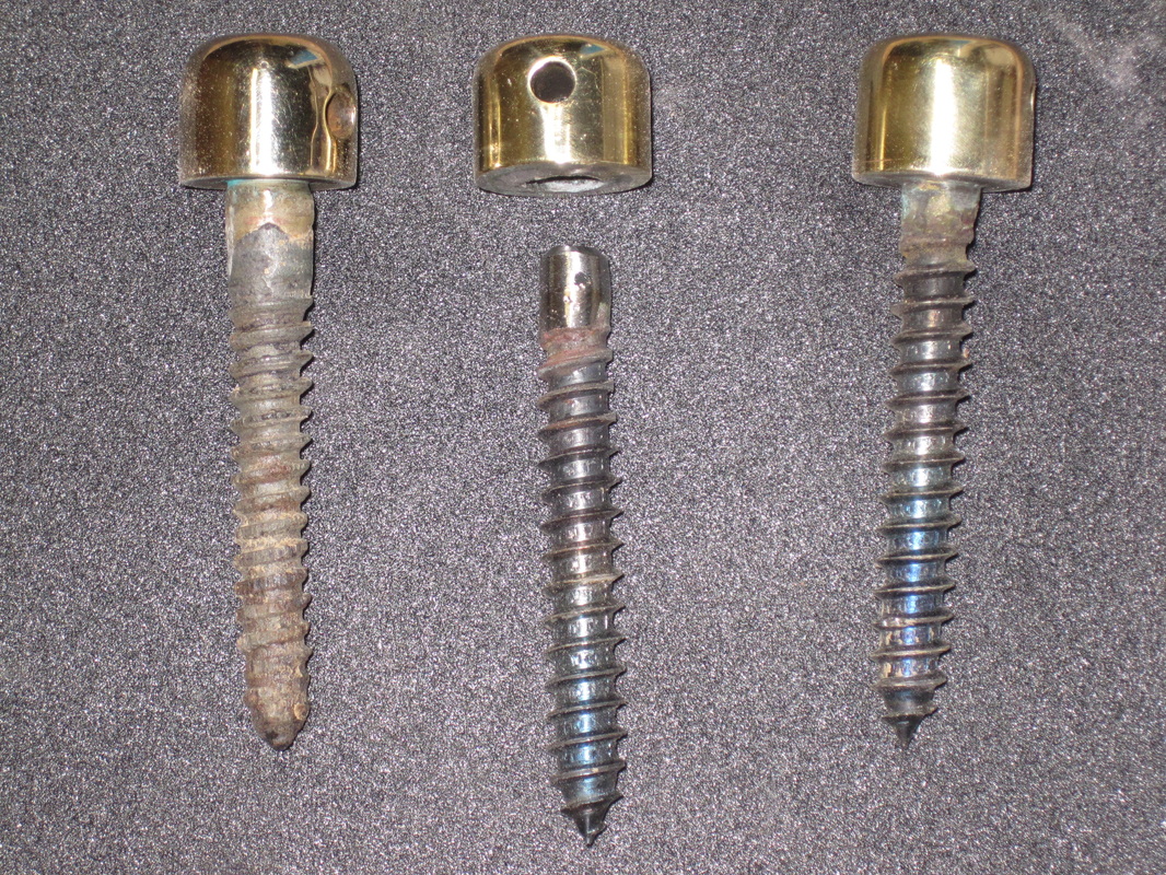
Original top screw on left, pieces and completed new screw on right.
|
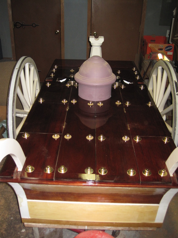
Top screws installed.
|
More parts in the paint booth with primer.
|
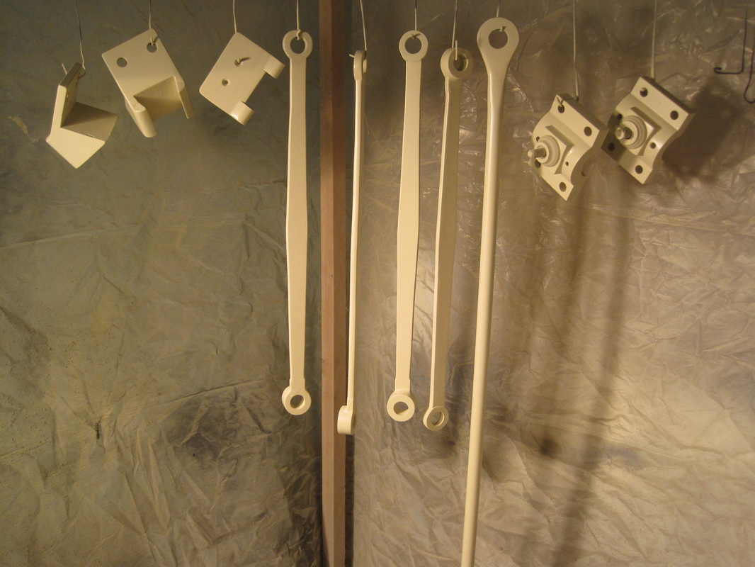
And more parts.
|
Update 7/14/2014
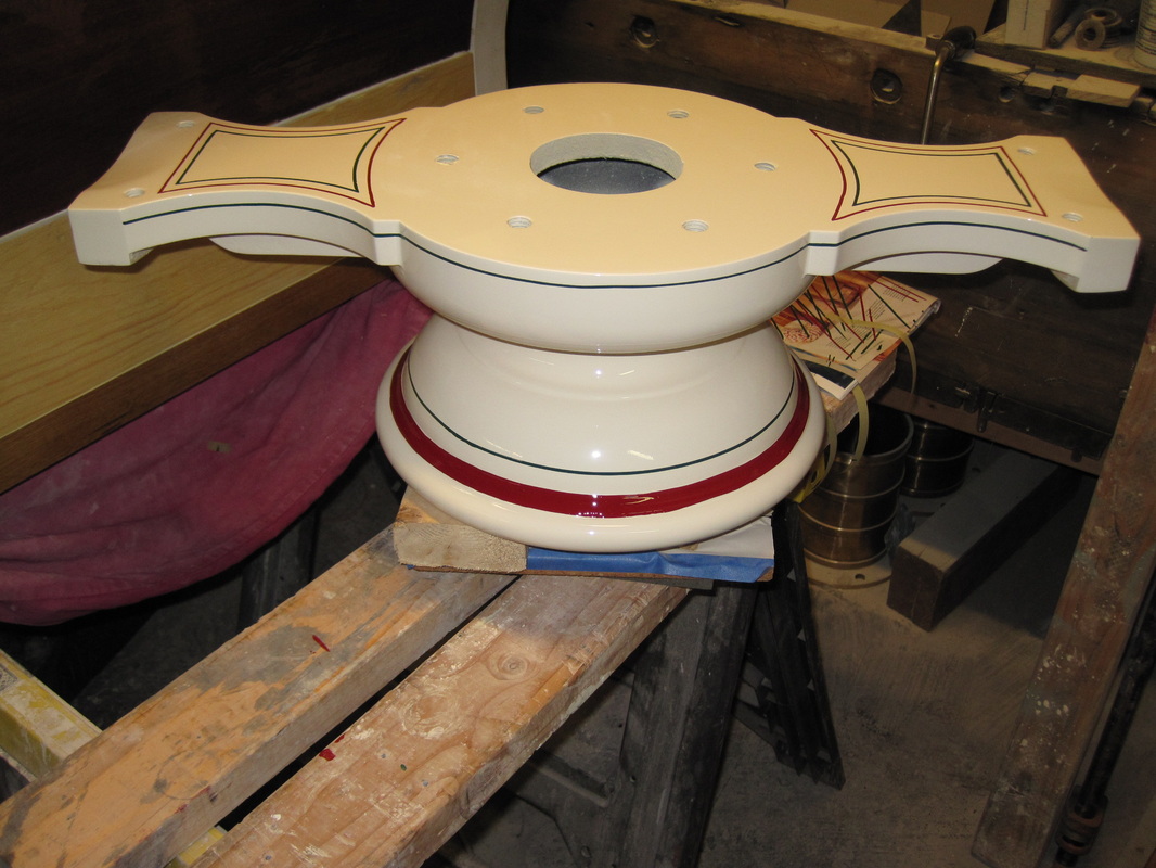
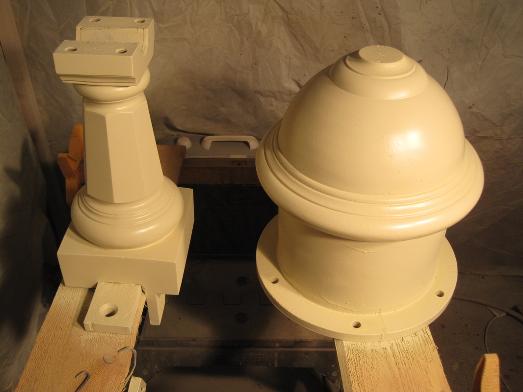
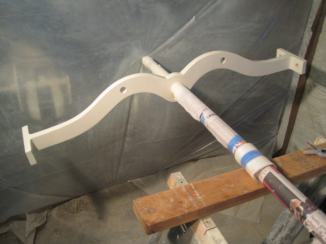
I've been busy spraying the finish coat of paint on several items including the pressure dome, front and rear rocker supports, and the rocker itself. I've also applied 23K gold leaf and started striping of these parts as well. The gold leaf was not difficult.
I've been busy spraying the finish coat of paint on several items including the pressure dome, front and rear rocker supports, and the rocker itself. I've also applied 23K gold leaf and started striping of these parts as well. The gold leaf was not difficult.
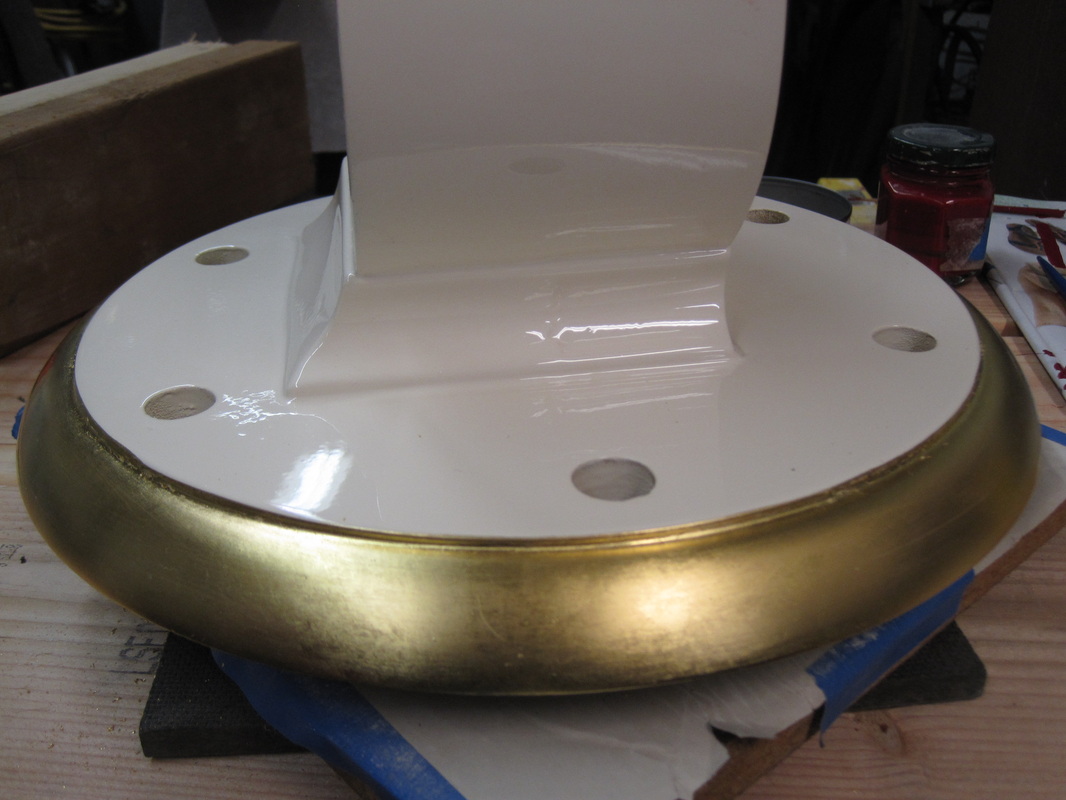
Gold leaf applied to front rocker support.
|
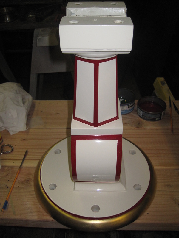
Striping on front rocker support
|
Finish coat of paint on the rocker
|
Update 10/23/2014
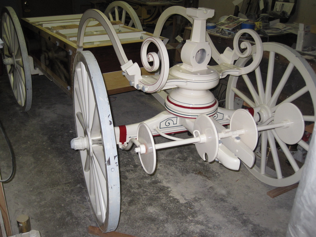
Sorry for the long time since the last update. Work on the handtub slowed over the summer due to other commitments. Summer civil war reenacting as well as more involvement with the Oregon Fire Service Museum. I finished painting and striping the pressure dome and rocker supports and installed them on the handtub. I also constructed a tongue for it. The original one had been lost so I had to design one based on photos and observations of originals. Typically they were Ash, which is light and strong, which is the wood I used. I laminated 2 pieces together and then cut and carved them to get the proper shape. Originals had iron reinforcing straps on the top and bottom and I made those as well. I also had to make the handle that is located at the end of the tongue with the handholds and guide for the drag rope. I still have to assemble all those parts and attach the tongue to the handtub. I also derusted the brakes, which are the large metal arms on each side of the handtub that hold the wood handles that are pumped by the firemen. One of the brakes had a severe bend and I had to heat it and force it back into shape. Then I went at them with a wire wheel and disc sander to remove the rust. After that I applied the phosphoric acid treatment and the first coat of primer, followed by sanding, filler, and another coat of primer.
Sorry for the long time since the last update. Work on the handtub slowed over the summer due to other commitments. Summer civil war reenacting as well as more involvement with the Oregon Fire Service Museum. I finished painting and striping the pressure dome and rocker supports and installed them on the handtub. I also constructed a tongue for it. The original one had been lost so I had to design one based on photos and observations of originals. Typically they were Ash, which is light and strong, which is the wood I used. I laminated 2 pieces together and then cut and carved them to get the proper shape. Originals had iron reinforcing straps on the top and bottom and I made those as well. I also had to make the handle that is located at the end of the tongue with the handholds and guide for the drag rope. I still have to assemble all those parts and attach the tongue to the handtub. I also derusted the brakes, which are the large metal arms on each side of the handtub that hold the wood handles that are pumped by the firemen. One of the brakes had a severe bend and I had to heat it and force it back into shape. Then I went at them with a wire wheel and disc sander to remove the rust. After that I applied the phosphoric acid treatment and the first coat of primer, followed by sanding, filler, and another coat of primer.
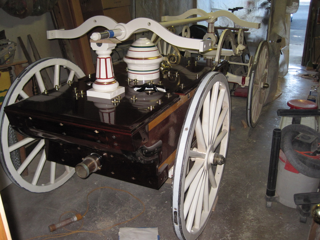
Handtub with rocker and pressure dome installed.
To be continued..... |
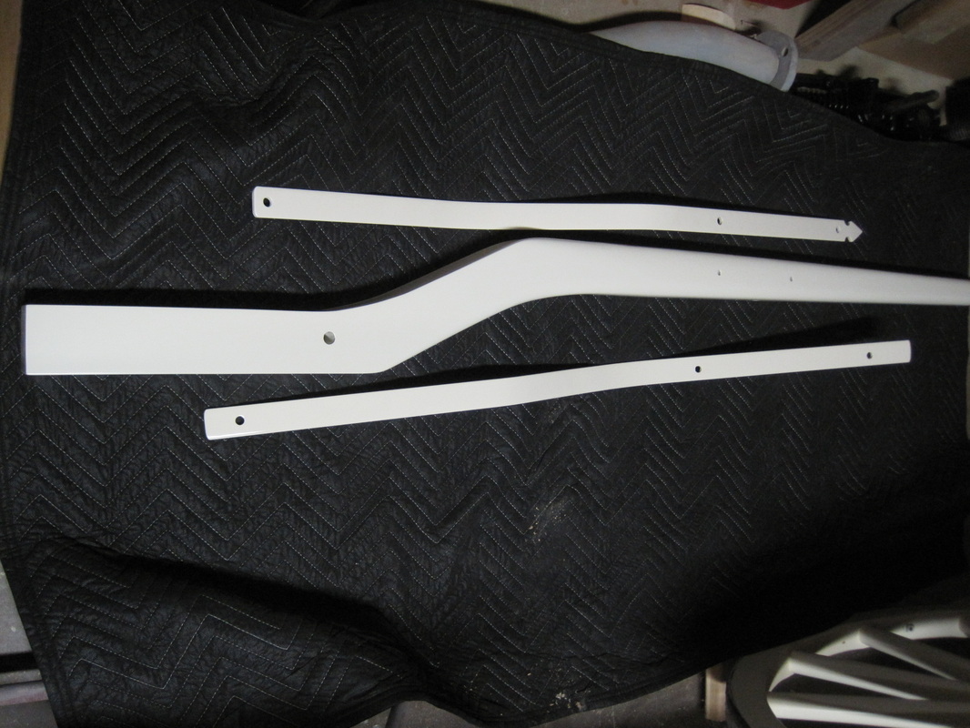
Tongue and iron reinforcing straps
|
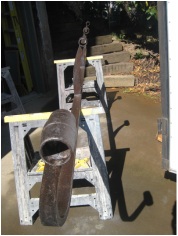
Brake with phosphate treatment.
|
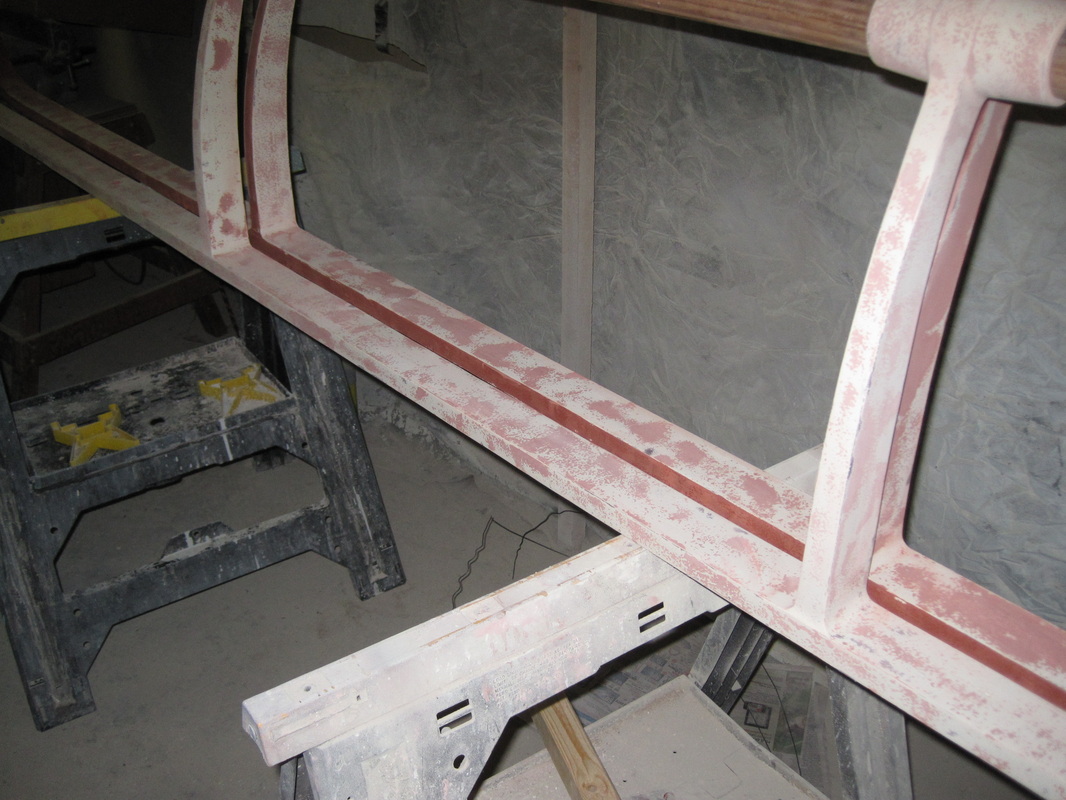
Brakes after primer, filling, and sanding.
|