Update 2/4/2013
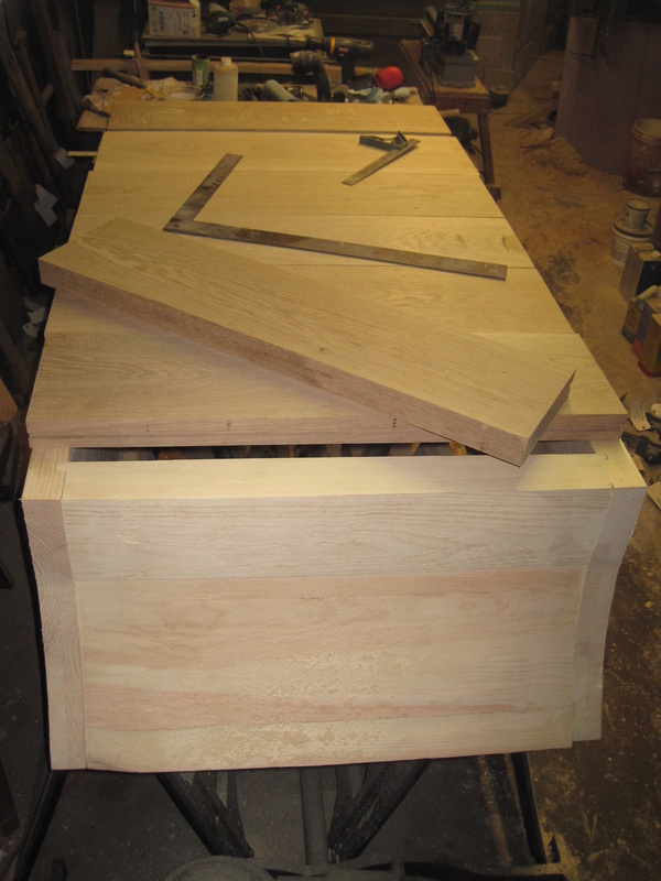
I make another trip to Crosscut Hardwoods to pick up the Eastern White Pine for the sides and ends of the tub as well as the White Oak for the bottom. The pine is not available in the wide widths that I need so I will have to edge glue it. Some of the original pieces were glued up to make up the width or thickness needed so I’m not cheating here too much. I start by cutting the sides, using the originals as patterns.
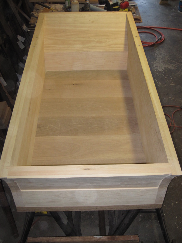
Each side gets a groove cut into the inside face that will accept a tongue cut on the end pieces to form a tongue and groove joint. The front and back of the tub are the most difficult to shape. The front piece includes a concave curve on the front face. The back piece has a convex curve and is nearly 4” thick at the thickest point. Both the back and front are made up of 2 pieces that meet at an angle. There is no evidence that this joint on the original tub was glued or had any type of sealant but it needs to be relatively watertight. These two pieces were held together on the old tub by 2 square nails which may or may not be original.
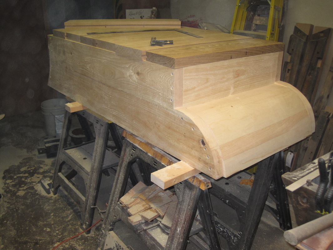
I cut templates for these pieces using the original pieces as patterns. The convex rear piece I shaped using a plane, using the template to check the shape as I go. The front piece was more challenging. With a tip from a cabinetmaker friend (thanks Royce) I make a jig with a matching curve and use a router sliding on
rails to cut the curve. I then cut the ends on each piece to form the tongues and test fit it all together. I have to adjust the angles slightly to get a tight fit. I left the pieces a little long on top so I can plane them down to match the sides. I assemble the pieces using the stay bolts and screws as per the original. It ends up square and true with tight joints.
I make another trip to Crosscut Hardwoods to pick up the Eastern White Pine for the sides and ends of the tub as well as the White Oak for the bottom. The pine is not available in the wide widths that I need so I will have to edge glue it. Some of the original pieces were glued up to make up the width or thickness needed so I’m not cheating here too much. I start by cutting the sides, using the originals as patterns.
Each side gets a groove cut into the inside face that will accept a tongue cut on the end pieces to form a tongue and groove joint. The front and back of the tub are the most difficult to shape. The front piece includes a concave curve on the front face. The back piece has a convex curve and is nearly 4” thick at the thickest point. Both the back and front are made up of 2 pieces that meet at an angle. There is no evidence that this joint on the original tub was glued or had any type of sealant but it needs to be relatively watertight. These two pieces were held together on the old tub by 2 square nails which may or may not be original.
I cut templates for these pieces using the original pieces as patterns. The convex rear piece I shaped using a plane, using the template to check the shape as I go. The front piece was more challenging. With a tip from a cabinetmaker friend (thanks Royce) I make a jig with a matching curve and use a router sliding on
rails to cut the curve. I then cut the ends on each piece to form the tongues and test fit it all together. I have to adjust the angles slightly to get a tight fit. I left the pieces a little long on top so I can plane them down to match the sides. I assemble the pieces using the stay bolts and screws as per the original. It ends up square and true with tight joints.
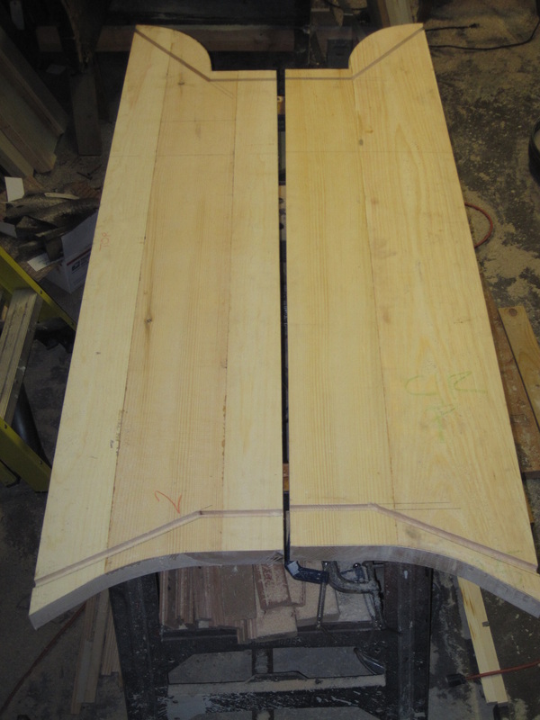
Tub sides
|
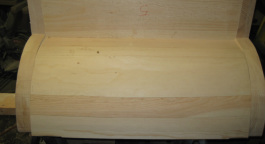
Convex back, upside down in this view
|
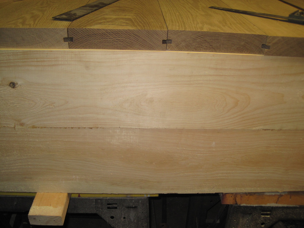
New front piece on bottom with old piece on top to check fit. The hole was a later addition and will not be reproduced.
|
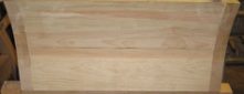
Complete new front bottom section is flat, top section is concave.
|
Update 2/18/2013
With the sides and ends all assembled I turn the tub upside down so I can work on the bottom.
The original bottom consists of boards of random width from 8”-16” wide. The widest I can find is
about 10”, already planed to 2” thick. It is really nice wood with good straight grain and only a couple of tiny knots. I cut them to length, rip them as wide as possible, and clean up the edges on the jointer. I use my
router to cut the grooves for the splines that will keep the boards aligned and watertight. I drill and
countersink the holes for the screws which are on 3” spacing. These are big screws, #16x3-1/2” , slotted heads of course, and the bits for my cordless drill just don’t engage the large slots in these screws securely. A quick trip to my mother’s antique shop and I have an old but apparently unused flat blade bit for my hand brace. A little wax on the threads for lubrication and the screws go in easily. I leave the splines out at this point since I know the bottom will be coming apart again. I work my way along the bottom, also locating and drilling the holes through the bottom boards for the vertical stay bolts as I go. I rip the last board to the proper width and attach it. I planned the board widths so that I don’t end up with a skinny piece. I turn the tub back right side up and admire the progress. It is of course much heavier now.
|
|
|
|
Update 3/1/2013
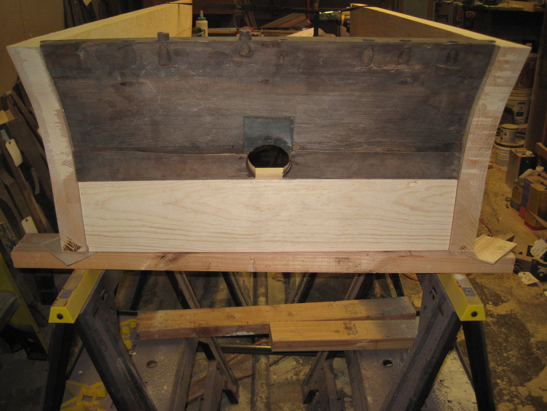
The first load of parts is finished at the metal stripper right on schedule and I pick them up. The next step is to attach the crane arms to the front of the new box. Since the inside of the box front has a sharp angle and the arms are curved, a groove was cut at the thickest point to allow the arms to fit the front more closely. Also, a small notch is cut part way into the bottom so that the end of the bottom leg of the arm can fit in. The bottom boards were missing at this point on the original box so I cut the notch at the location and size that allows the location of the mounting bolts to match the original box. Since my shop floor slopes, I shim the box so it is level and use a level to make sure the front of the 2 arms are aligned. It takes a few hours hours per side to get the mounting holes located and drilled and the notches located and cut and the arms bolted on. The arms are heavy and awkward to hold in place while marking the locations. After multiple trials and chiseling a little deeper here, a little wider there, and no errors, they are in place.
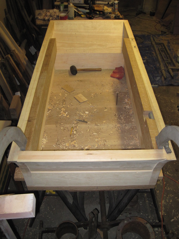
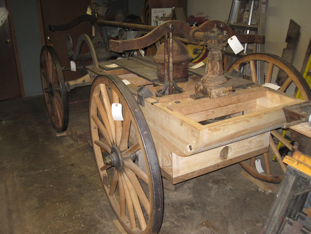
Once the arms are attached, the side beams can be fit. As I mentioned earlier, these beams have recesses cut into the back side to fit around the arms and the bolts that attach the arms. These also will have notches cut into the top edge to hold the crossmembers that support the top.
The first load of parts is finished at the metal stripper right on schedule and I pick them up. The next step is to attach the crane arms to the front of the new box. Since the inside of the box front has a sharp angle and the arms are curved, a groove was cut at the thickest point to allow the arms to fit the front more closely. Also, a small notch is cut part way into the bottom so that the end of the bottom leg of the arm can fit in. The bottom boards were missing at this point on the original box so I cut the notch at the location and size that allows the location of the mounting bolts to match the original box. Since my shop floor slopes, I shim the box so it is level and use a level to make sure the front of the 2 arms are aligned. It takes a few hours hours per side to get the mounting holes located and drilled and the notches located and cut and the arms bolted on. The arms are heavy and awkward to hold in place while marking the locations. After multiple trials and chiseling a little deeper here, a little wider there, and no errors, they are in place.
Once the arms are attached, the side beams can be fit. As I mentioned earlier, these beams have recesses cut into the back side to fit around the arms and the bolts that attach the arms. These also will have notches cut into the top edge to hold the crossmembers that support the top.
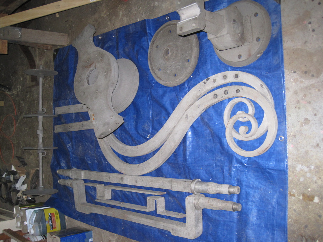
First load of parts back from the stripper.
|
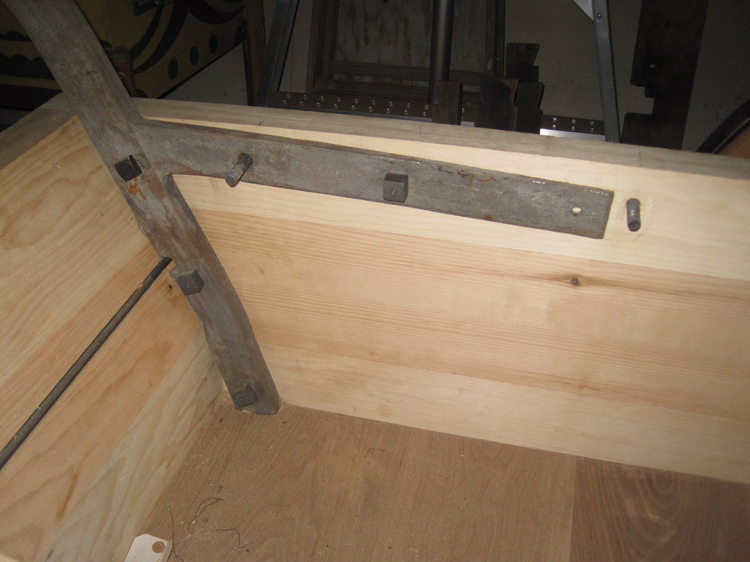
Crane arm fit to the tub
|
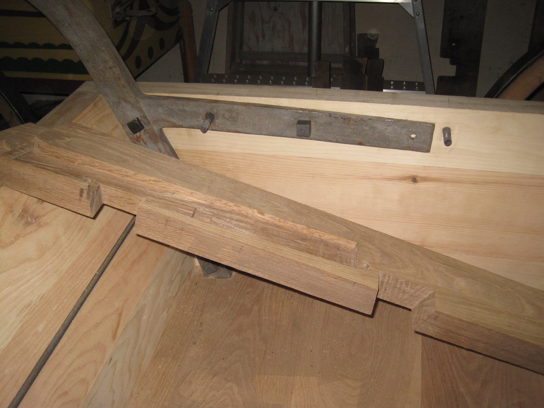
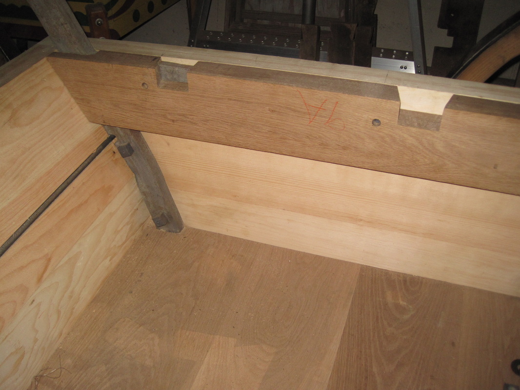
Back side of the side beam cut to fit over the arm.
|
Side beam fit over the arm.
|
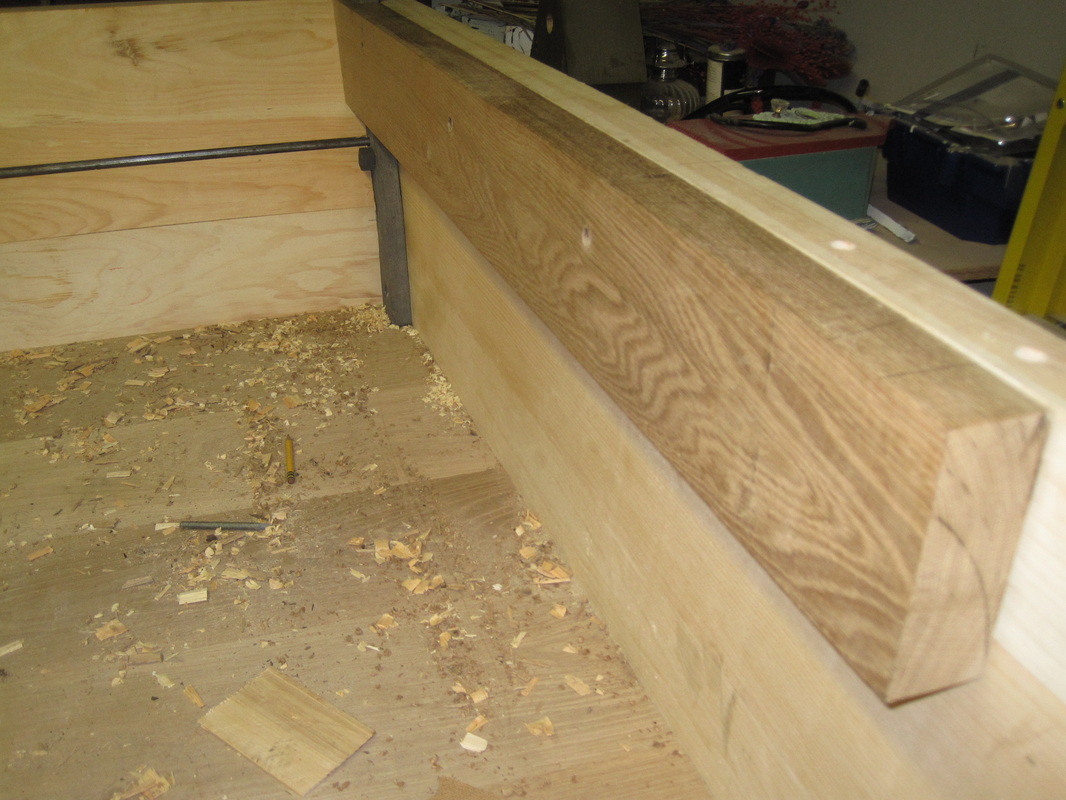
Both arms and beams in place.
|
Update 3/13/2013
With the side beams in place I can locate and cut all of the notches that the top crossmembers fit into. The crossmembers serve two purposes. First, they support the top cover of the tub. The foreman of the fire crew would typically stand on top of the tub and direct his crew from that vantage point and therefor they need to support that weight. Second, they tie the sides of the tub together to prevent them from bowing outwards when the tub is filled with water. For the second reason they are "keyed" into the side beams. The side beams are through bolted to the tub sides in several locations. The original beams and crossmembers are in good enough condition to use for patterns. With careful work with a saw and chisel I get all of the notches cut and the crossmember ends shaped to fit the notches. The crossmembers extend above the top of the tub sides and the beams 1/2". This is the thickness of the mahogany trim that fits on the top edge of the tub. That allows the top boards to sit flush on the tub edge and the crossmembers. 4 of the 6 crossmembers fit into the side beams with the rearmost 2 fitting in notches in the side of the tub itself. Crossmember #5 is a large one that supports the rear bearing column for the rocker assembly. I will hold off on cutting that notch until I reassemble and install the front truck assembly (which holds the front bearing column) so I can verify the correct location of that crossmember based on the bearing spacing of the rocker. It should fit tight to the back end of the side beams. Crossmember #6 is missing. I only have the notches in the tub to go by and they are partially rotted away but I make a guess at it. Since this seems to be a nearly one of a kind piece, who's going to tell me I'm wrong anyway? The crossmembers just sit in place and are not attached in any way.
With the side beams in place I can locate and cut all of the notches that the top crossmembers fit into. The crossmembers serve two purposes. First, they support the top cover of the tub. The foreman of the fire crew would typically stand on top of the tub and direct his crew from that vantage point and therefor they need to support that weight. Second, they tie the sides of the tub together to prevent them from bowing outwards when the tub is filled with water. For the second reason they are "keyed" into the side beams. The side beams are through bolted to the tub sides in several locations. The original beams and crossmembers are in good enough condition to use for patterns. With careful work with a saw and chisel I get all of the notches cut and the crossmember ends shaped to fit the notches. The crossmembers extend above the top of the tub sides and the beams 1/2". This is the thickness of the mahogany trim that fits on the top edge of the tub. That allows the top boards to sit flush on the tub edge and the crossmembers. 4 of the 6 crossmembers fit into the side beams with the rearmost 2 fitting in notches in the side of the tub itself. Crossmember #5 is a large one that supports the rear bearing column for the rocker assembly. I will hold off on cutting that notch until I reassemble and install the front truck assembly (which holds the front bearing column) so I can verify the correct location of that crossmember based on the bearing spacing of the rocker. It should fit tight to the back end of the side beams. Crossmember #6 is missing. I only have the notches in the tub to go by and they are partially rotted away but I make a guess at it. Since this seems to be a nearly one of a kind piece, who's going to tell me I'm wrong anyway? The crossmembers just sit in place and are not attached in any way.
Notches in side beams.
|
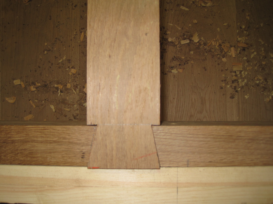
Keyed ends of crossmember. Some are keyed on both sides, some on only one side.
|
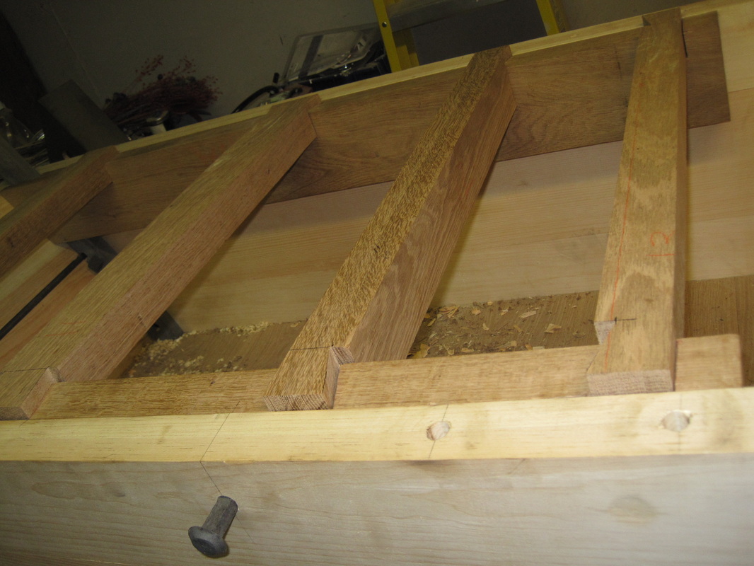
Crossmembers in place. Some are notched on the bottom so that a deeper crossmemeber can fit in a shallow notch.
|
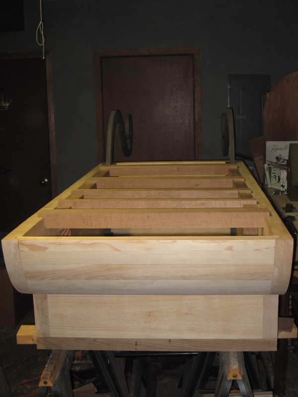
Crossmembers #1-4 and #6 installed.
|
Update 3/28/2013
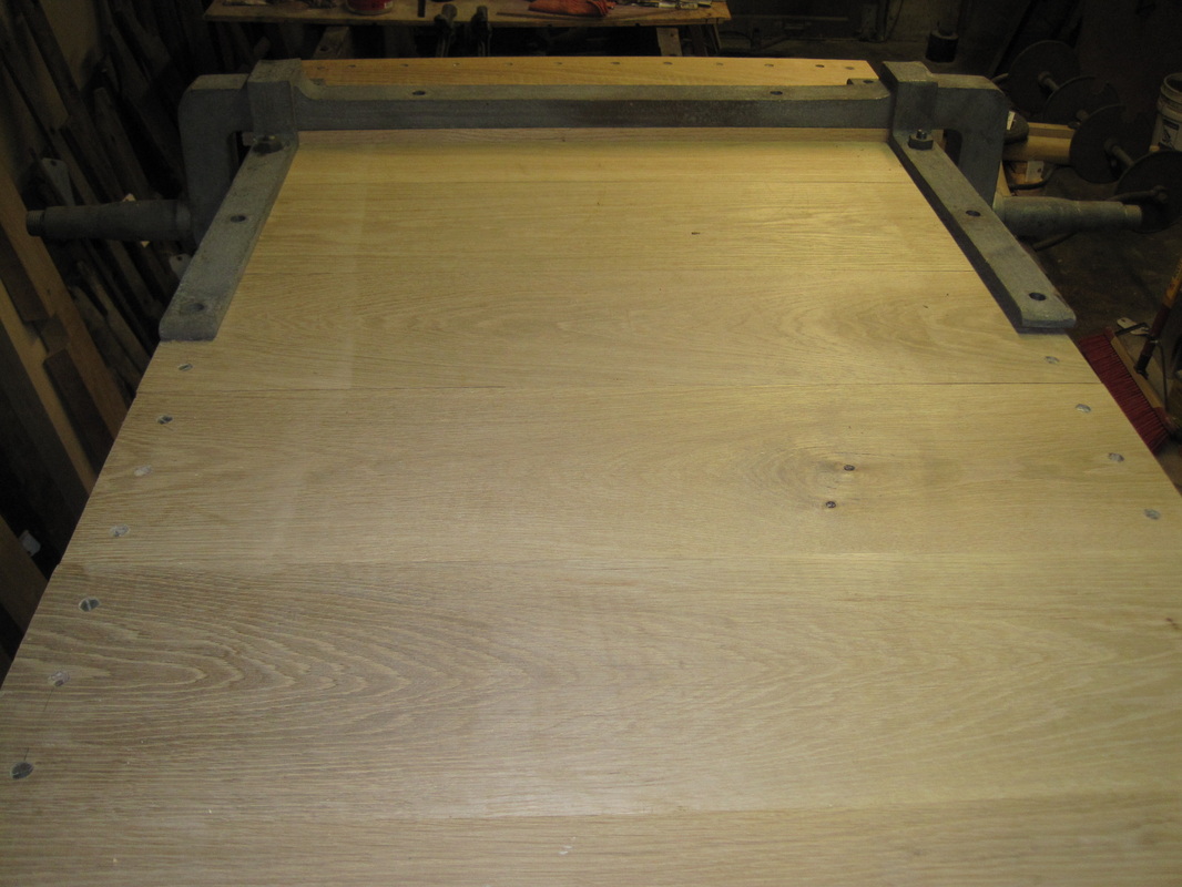
So once all of the crossmembers (except #5) are fit, I take them all back out, as well as removing the beams and crane arms. I flip the tub over again to fit the rear axle. The axle is 2-1/2" solid square steel and is held in place by two carriage bolts through the tub bottom and a bracket on each side. Each bracket is attached by the two stay bolts that run down through the sides, and 3 large lag bolts. There is a wood spacer between the axle and bottom of the tub. I assume this was intended to take any wear and prevent damage to the tub bottom. The original is quite worn, especially near the ends, so it is replaced with a new piece. Once the rear axle is attached I flip it back over and replace the crane arms and beams.
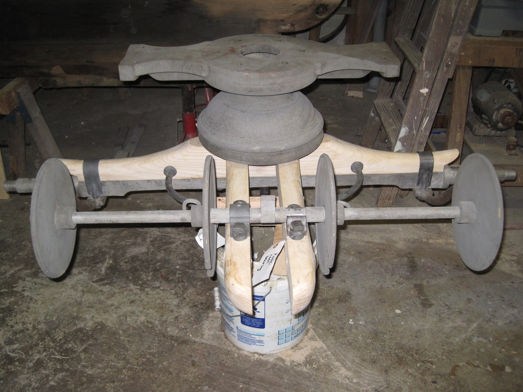
I turn my attention to the front truck. A "truck" in this case is an axle assembly that that pivots in the center to allow the wheels to steer. As I'm working on all of the iron pieces I file or grind off burrs or similar damage. There are at least a dozen pieces that make up the front truck and I proceed carefully with drilling the necessary holes in the wood front axle since I don't want to have to recut it. The truck holds the drag rope reel and the tongue will also attach to it. It also supports a tool box on the arms that extend out the back.
I have also cleaned out all of the old grease from inside the wheel hubs, sandblasted the outside of them and wire brushed the iron tires.
So once all of the crossmembers (except #5) are fit, I take them all back out, as well as removing the beams and crane arms. I flip the tub over again to fit the rear axle. The axle is 2-1/2" solid square steel and is held in place by two carriage bolts through the tub bottom and a bracket on each side. Each bracket is attached by the two stay bolts that run down through the sides, and 3 large lag bolts. There is a wood spacer between the axle and bottom of the tub. I assume this was intended to take any wear and prevent damage to the tub bottom. The original is quite worn, especially near the ends, so it is replaced with a new piece. Once the rear axle is attached I flip it back over and replace the crane arms and beams.
I turn my attention to the front truck. A "truck" in this case is an axle assembly that that pivots in the center to allow the wheels to steer. As I'm working on all of the iron pieces I file or grind off burrs or similar damage. There are at least a dozen pieces that make up the front truck and I proceed carefully with drilling the necessary holes in the wood front axle since I don't want to have to recut it. The truck holds the drag rope reel and the tongue will also attach to it. It also supports a tool box on the arms that extend out the back.
I have also cleaned out all of the old grease from inside the wheel hubs, sandblasted the outside of them and wire brushed the iron tires.
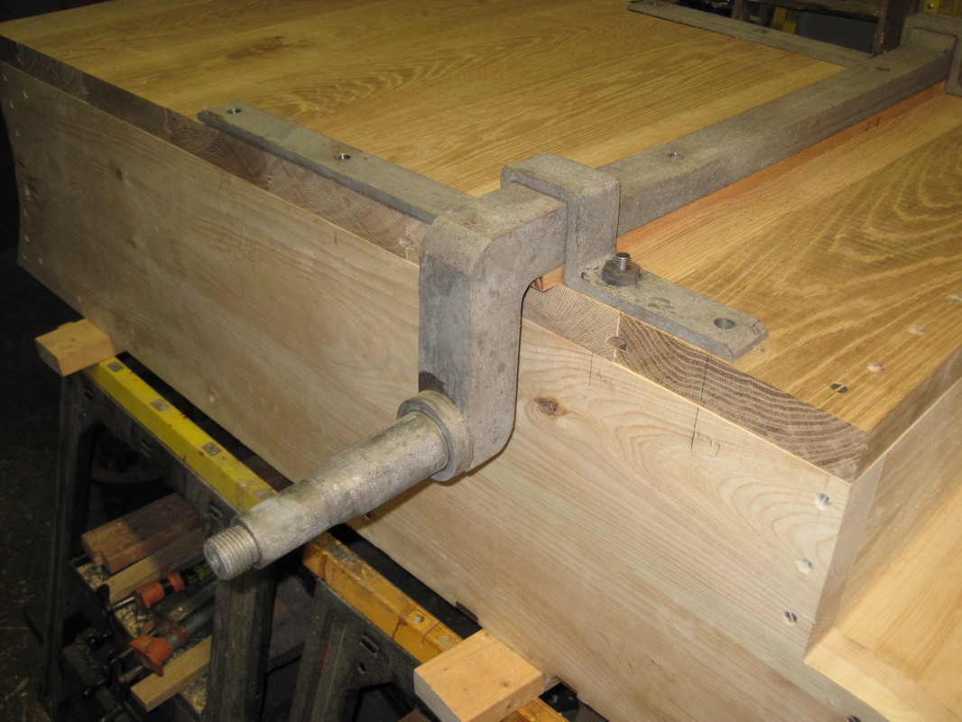
Rear axle attachment
|
Rear axle mounted with spacer
|
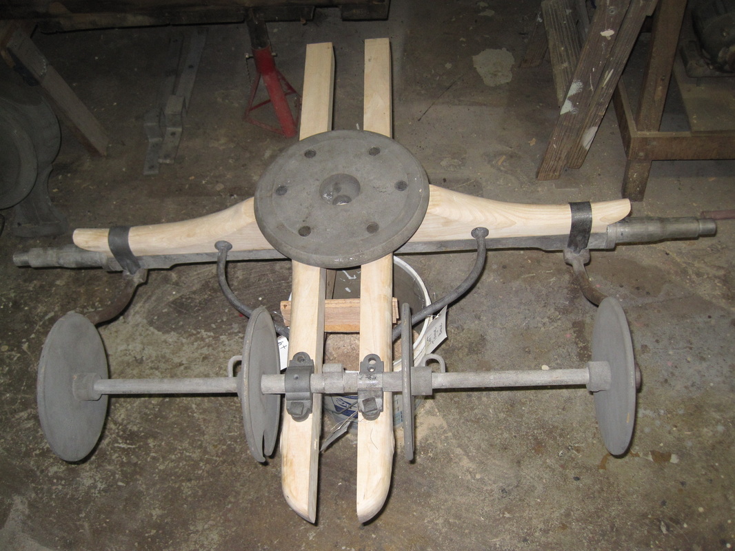
Front truck assembled
|
Front truck with upper part of fifth wheel.
|
Update 4/22/2013
I mate the front truck up to the crane arms and put the all wheels back on. Once the front truck is attached I can bolt on the column that contains the front bearing for the rocker arm. I set the pump back into place so I can mark the location of a recess and hole that needs to be cut into the bottom of the tub. This portion of the old tub was missing. The recess accomodates the lip of the flange that attaches the suction inlet to the main pump body and the hole in the bottom is for the handle that operates the suction valve. I also mark and cut the opening in the back of the tub for the suction inlet pipe. I draft a couple of helpers to lift the rocker arm into position and I support the rear of it on wood blocks. The rocker has bearing journals so the relative position of the front and rear bearings is precisely fixed. I attach the rear bearing column to the rocker arm allowing it to hang free. This way I can locate the proper postion of the rear crossmember. Fortunately it lines up in the same position as the old one, tight to the back end of the side beams. I carefully chisel out the notches in the sides of the tub and drop the large crossmember into place and mark and drill the holes to mount the bearing column and the hold down bolts. After everything is assembled, it all is taken apart again. The rest of the iron pieces are loaded up and delivered to the stripper and the box is disassembled in preparation for veneering and painting.
I mate the front truck up to the crane arms and put the all wheels back on. Once the front truck is attached I can bolt on the column that contains the front bearing for the rocker arm. I set the pump back into place so I can mark the location of a recess and hole that needs to be cut into the bottom of the tub. This portion of the old tub was missing. The recess accomodates the lip of the flange that attaches the suction inlet to the main pump body and the hole in the bottom is for the handle that operates the suction valve. I also mark and cut the opening in the back of the tub for the suction inlet pipe. I draft a couple of helpers to lift the rocker arm into position and I support the rear of it on wood blocks. The rocker has bearing journals so the relative position of the front and rear bearings is precisely fixed. I attach the rear bearing column to the rocker arm allowing it to hang free. This way I can locate the proper postion of the rear crossmember. Fortunately it lines up in the same position as the old one, tight to the back end of the side beams. I carefully chisel out the notches in the sides of the tub and drop the large crossmember into place and mark and drill the holes to mount the bearing column and the hold down bolts. After everything is assembled, it all is taken apart again. The rest of the iron pieces are loaded up and delivered to the stripper and the box is disassembled in preparation for veneering and painting.
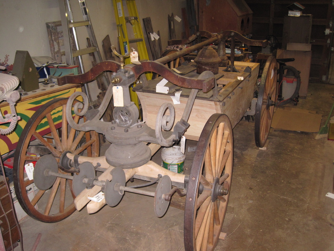
Front view with pump and rocker arm in place
|
Back view with hole for suction inlet
|
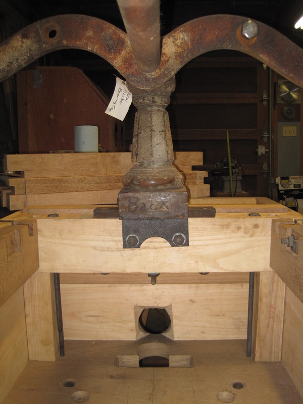
Rocker arm column and crossmember
|
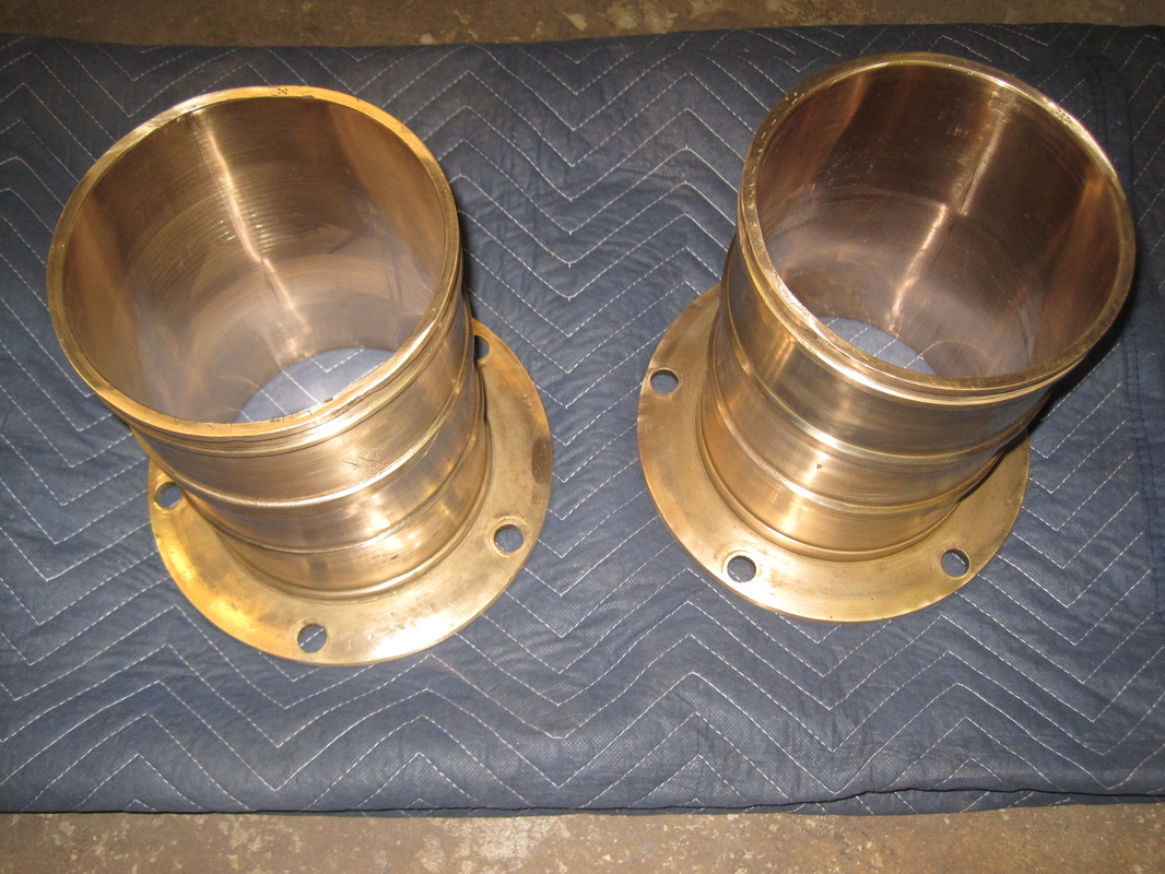
Pump cylinders cleaned and honed.
|
Update 6/7/2013
Sorry for the long delay, Civil War reenacting season has started. After everything is disassembled again the next step is to paint the wood parts that were originally painted. Not much of the original paint remains so on some pieces I am guessing whether or not they were originally painted or left bare. I don't intend to leave any wood bare so it will all get painted or varnished. The inside of the tub was originally painted and apparently before it was assembled and it looks like it was white. So all of the tub pieces get primed and then painted with 2 coats white marine grade oil based gloss enamel paint.
After all of this painting is complete I begin the veneering process. I found a nice lot of slightly figured honduran mahogany raw veneer sheets large enough to cover the tub with no joints needed. I also invested in a vaccum bag setup for clamping the veneer to the tub while the glue dries. In short, the kit uses a venturi connected to my air compressor to create a vacuum in a plastic bag into which the veneered item is placed. The venturi creates a vacuum which allows atmosheric pressure of about 1700 lbs. per square foot to evenly clamp the veneer to the subtrate. With large pieces and especially curved pieces like I am working with here I have found it impossible to evenly clamp veneer with any type of mechanical clamp and not end up with bubbles or unglued areas. For a description of the setup, see http://www.joewoodworker.com/veneering/welcome.htm
I used an old CO2 fire extinguisher cylinder for my vacuum tank and it worked perfectly. I have a few of those around. I used an exterior grade waterproof glue.
Sorry for the long delay, Civil War reenacting season has started. After everything is disassembled again the next step is to paint the wood parts that were originally painted. Not much of the original paint remains so on some pieces I am guessing whether or not they were originally painted or left bare. I don't intend to leave any wood bare so it will all get painted or varnished. The inside of the tub was originally painted and apparently before it was assembled and it looks like it was white. So all of the tub pieces get primed and then painted with 2 coats white marine grade oil based gloss enamel paint.
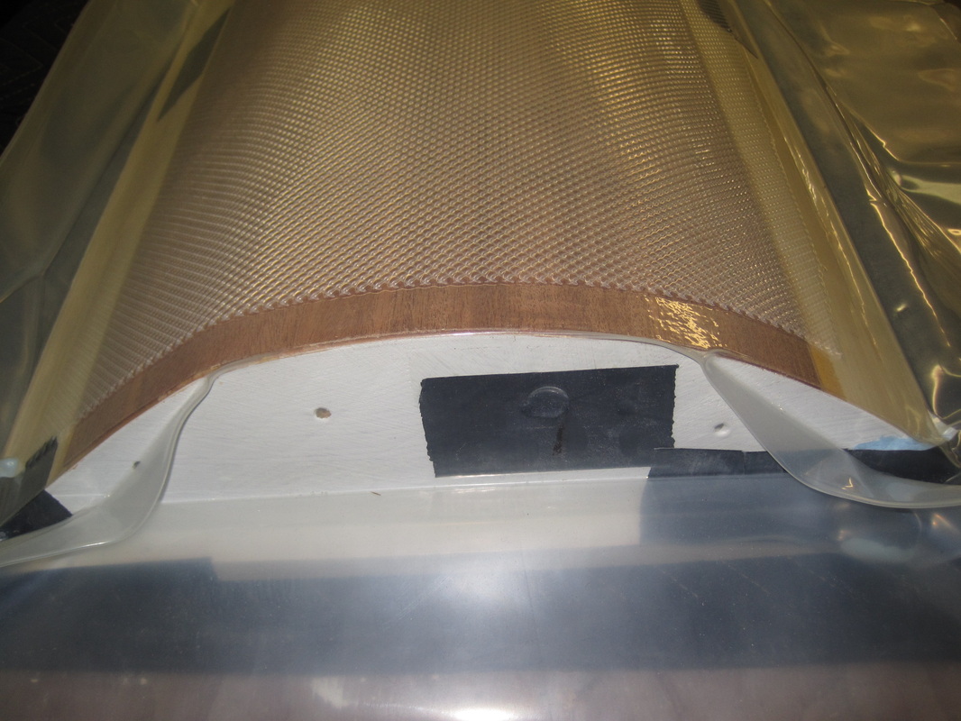
After all of this painting is complete I begin the veneering process. I found a nice lot of slightly figured honduran mahogany raw veneer sheets large enough to cover the tub with no joints needed. I also invested in a vaccum bag setup for clamping the veneer to the tub while the glue dries. In short, the kit uses a venturi connected to my air compressor to create a vacuum in a plastic bag into which the veneered item is placed. The venturi creates a vacuum which allows atmosheric pressure of about 1700 lbs. per square foot to evenly clamp the veneer to the subtrate. With large pieces and especially curved pieces like I am working with here I have found it impossible to evenly clamp veneer with any type of mechanical clamp and not end up with bubbles or unglued areas. For a description of the setup, see http://www.joewoodworker.com/veneering/welcome.htm
I used an old CO2 fire extinguisher cylinder for my vacuum tank and it worked perfectly. I have a few of those around. I used an exterior grade waterproof glue.
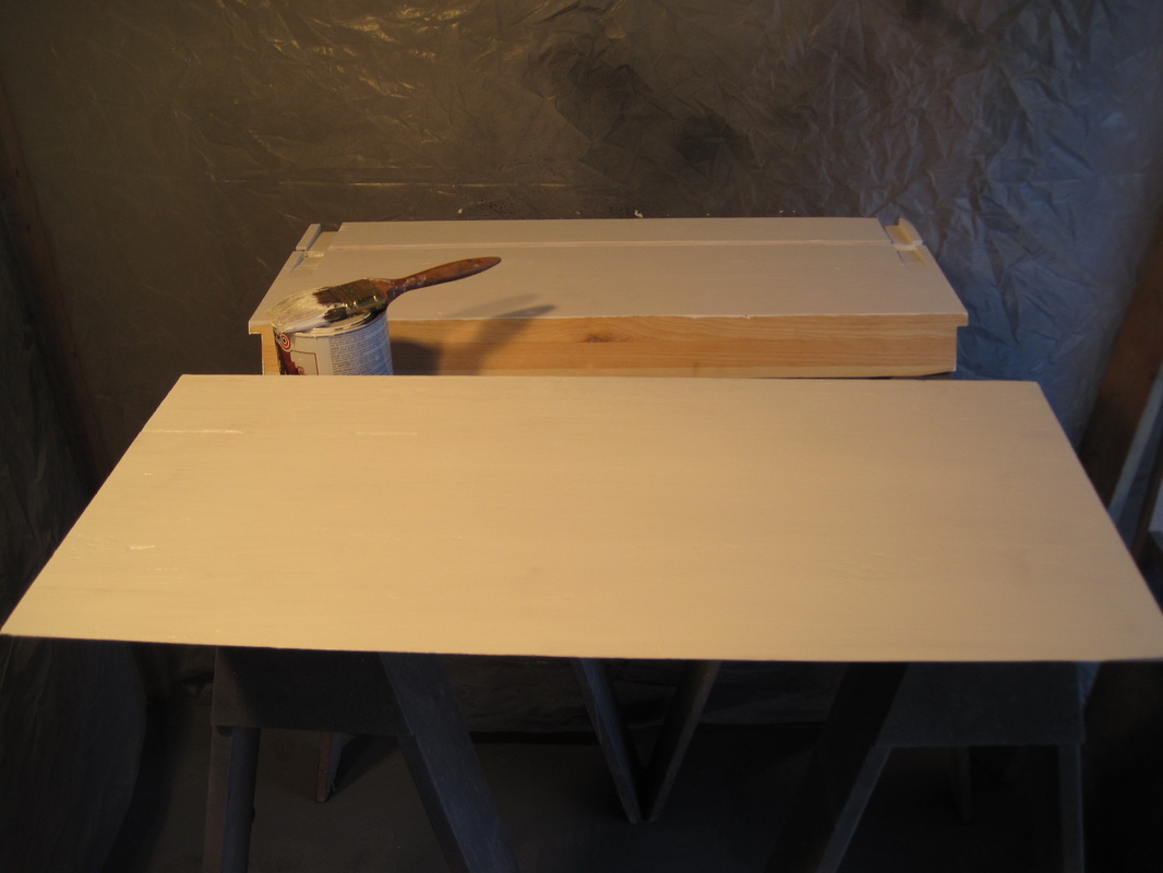
Painting the inside of the tub pieces.
|

Untrimmed veneer piece for one side.
|
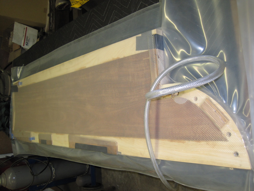
Venner trimmed to fit, glued, and clamped in the vacuum bag.
|
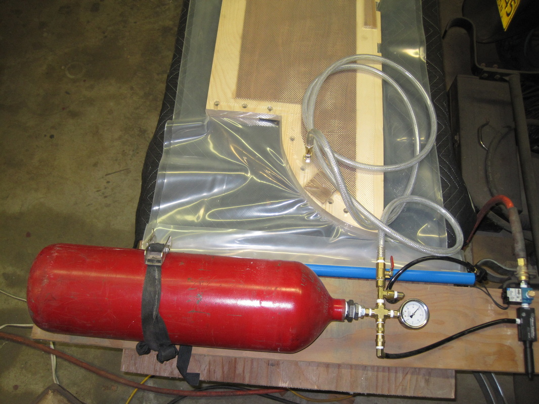
Vacuum bag setup
|
Rear curved piece.
|
Update 7/10/2013
After the veneer is applied, I lightly sand it and apply several coats of marine grade UV resistant gloss spar varnish. Mahogany is an open grain wood and several coats are needed to fill the grain and create a smooth glossy finish. With the veneer complete, I turn my attention to painting of the metal parts. All of the parts have been either sandblasted or chemically stripped of the old paint and rust. I sand them to reduce any rust pitting and to remove any dings or burrs acquired over the years. I apply a phosphate treatment followed by epoxy primer. After the epoxy primer comes several coats of primer surface, sanding after each coat with progressively finer grit paper. I apply spot putty as needed to fill any deep pits. After the final coat of primer I wet sand with 600 grit paper. The finish coat is single stage automotive acrylic enamel, tinted to match my guess of the original color. It is a slow process since I only have a small area for a painting enclosure. The process will be repeated in stages as the handtub is reassembled.
After the veneer is applied, I lightly sand it and apply several coats of marine grade UV resistant gloss spar varnish. Mahogany is an open grain wood and several coats are needed to fill the grain and create a smooth glossy finish. With the veneer complete, I turn my attention to painting of the metal parts. All of the parts have been either sandblasted or chemically stripped of the old paint and rust. I sand them to reduce any rust pitting and to remove any dings or burrs acquired over the years. I apply a phosphate treatment followed by epoxy primer. After the epoxy primer comes several coats of primer surface, sanding after each coat with progressively finer grit paper. I apply spot putty as needed to fill any deep pits. After the final coat of primer I wet sand with 600 grit paper. The finish coat is single stage automotive acrylic enamel, tinted to match my guess of the original color. It is a slow process since I only have a small area for a painting enclosure. The process will be repeated in stages as the handtub is reassembled.
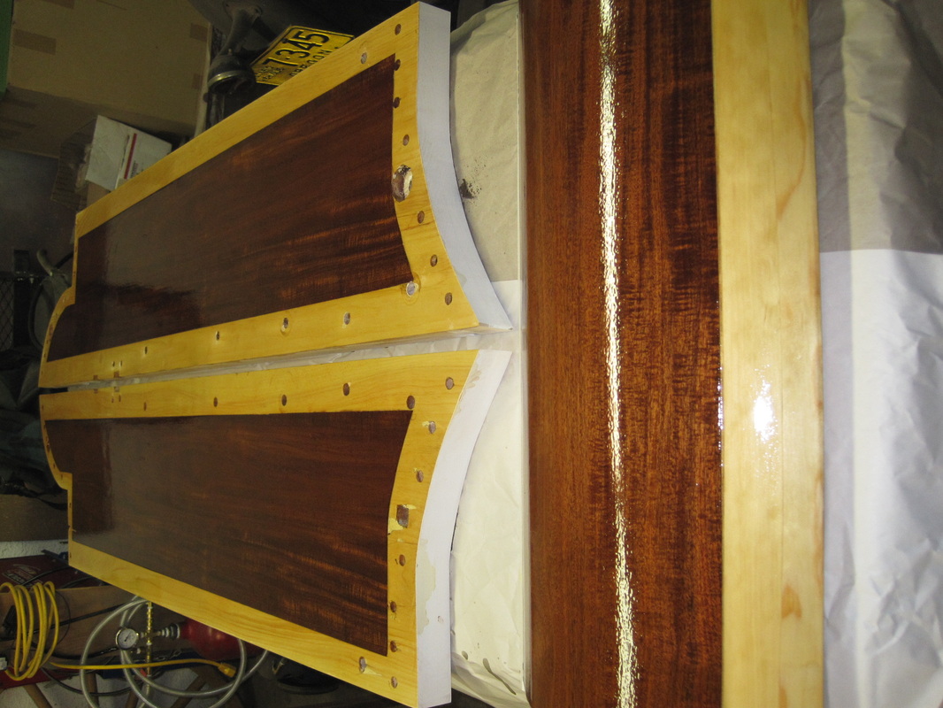
Several coats of spar varnish applied.
|
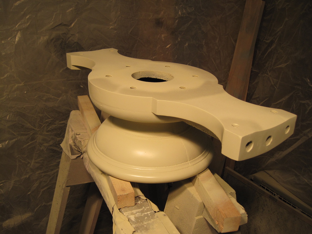
Primer surfacer applied.
|
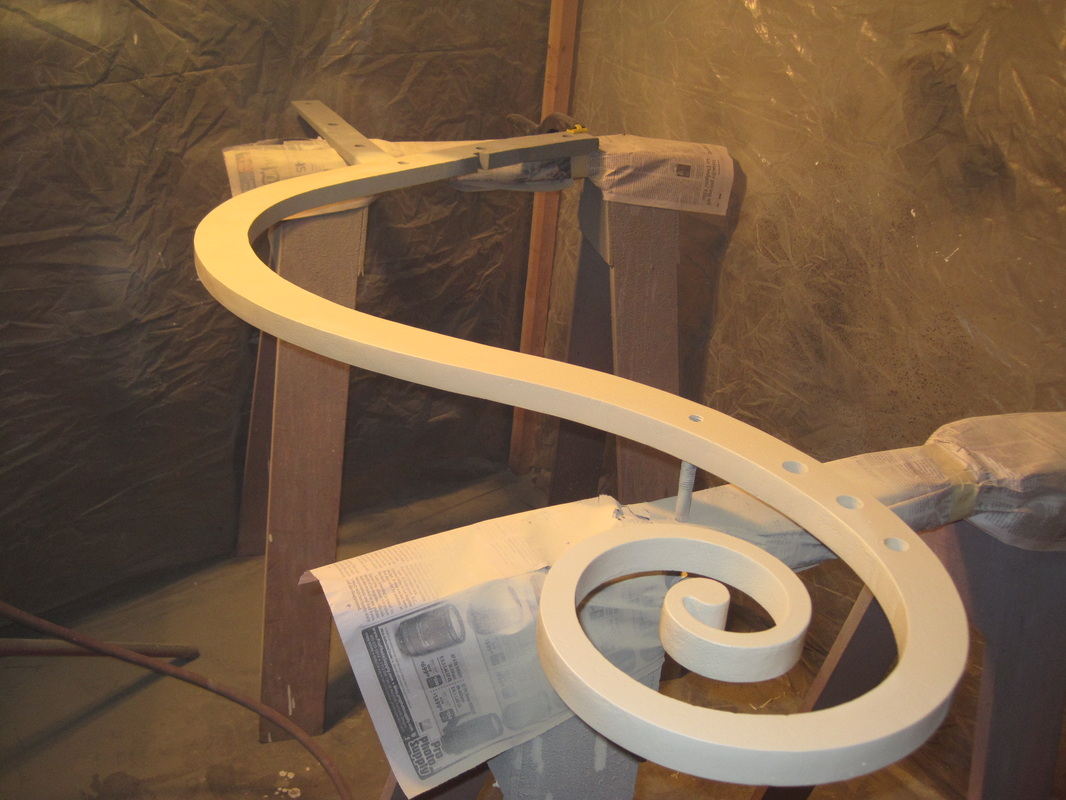
Finish coat of paint.
|